
Submarine cable center positioning and protection device

A center positioning and protection device technology, which is applied in cable installation, cable installation in underground pipelines, cable laying equipment, etc., can solve problems such as cable fatigue damage, cable failure to transmit power, power system paralysis, etc., to reduce corrosion and use The effect of long life and improved service life

Active Publication Date: 2016-03-30
ZHONGTIAN TECH SUBMARINE CABLE CO LTD
View PDF9 Cites 3 Cited by
  • Summary
  • Abstract
  • Description
  • Claims
  • Application Information

AI Technical Summary

Problems solved by technology

Therefore, the submarine cable will swing freely in the protective tube, especially at the outlet of the lower end of the protective tube, where the submarine cable is most severely affected by the ocean current. Fatigue and breakage of the cable causes the cable to be unable to transmit power, and eventually leads to the paralysis of the entire power system, resulting in huge economic losses
At present, the commonly used protection method is to use heavy objects to press the submarine cable out of the protective tube to prevent the movement of the submarine cable. This method can effectively control the movement of the submarine cable in a short period of time, but under the action of long-term ocean currents, the heavy objects will be washed away. The submarine cable can swing freely

Method used


Image

  • Submarine cable center positioning and protection device
  • Submarine cable center positioning and protection device

Examples


Embodiment Construction

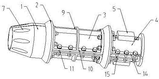
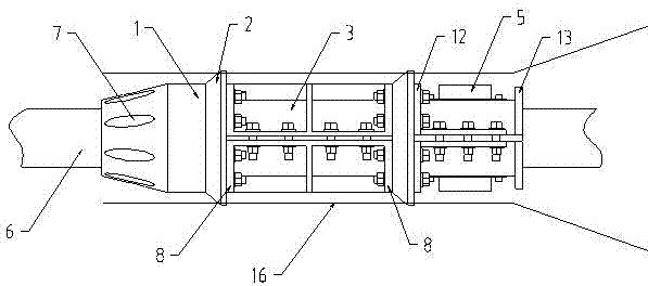
[0021] Such as figure 1 with figure 2 A submarine cable center positioning protection device shown includes a guide cone 1, a tapered ring 2, a positioning shaft 3 and a connecting shaft 4. The guide cone 1 is composed of two symmetrical parts, the head is a conical structure, and the end face is set Circumferential bolt holes 7; the tapered ring 2 is composed of two symmetrical parts, the outer surface is a tapered structure, and the end face is provided with a circular through hole; the positioning shaft 3 is composed of two symmetrical parts, and connecting flanges 8 are provided at both ends , the outer surface is provided with reinforcing ribs 9, and side plates 10 are provided on the edges of both sides. Bolt holes 11 are provided on the side plates 10. Through the bolt holes 11, the two symmetrical parts of the positioning axis 3 are connected by bolts, and the guide cone 1 and the cone are connected by bolts. Shaped ring 2 and positioning shaft 3; the connecting shaf...


PUM


Abstract

The invention discloses a submarine cable center positioning and protection device, and the device comprises a guide cone, a conical ring, a positioning shaft, and a connecting shaft. The guide cone consists of two symmetric parts, and the head part of the guide cone is in a conical structure. The conical ring consists of two symmetric parts, wherein an outer side surface of the conical ring is in a conical structure, and an end face of the conical ring is provided with an annular through hole. The positioning shaft consists of two parts, wherein an external surface is provided with a reinforcing rib, and two side edges are provided with side plates. The side plates are provided with bolts holes, and the symmetric parts of the positioning shaft are connected through the bolt holes and bolts. Moreover, the guide cone, the conical ring and the positioning ring are connected through bolts. The connecting shaft consists of two symmetric parts, wherein the head part of the connecting shaft is provided with a connecting flange, and two side edges of the connecting shaft are connected with the side plates. According to the invention, the device can enable a cable at a lower port of a protection tube to be limited at the center of the protection tube, can effectively control the swinging of a submarine cable in the protection tube, prevents the submarine cable to collide with the rigid protection tube, and avoids the fatigue damage of the submarine cable under the long-term action of ocean current. Meanwhile, the device is simple in structure, is convenient to install, is high in reliability, and is long in service life.

Description

technical field [0001] The invention relates to a submarine cable center positioning protection device, which is particularly suitable for center positioning protection of oil platforms and offshore wind power submarine cables in protection pipes. Background technique [0002] With the increasing demand for energy in my country, the development of offshore oil and gas and offshore wind power is also rapidly increasing. As an important medium for power transmission, submarine cables are of utmost importance to their safety and reliability during use. The oil platform or offshore wind power submarine cable is passed from the bottom of the sea to the top of the platform through a rigid protective tube. In order to pass through the tube smoothly, the inner diameter of the submarine cable protective tube is generally about 3 times the outer diameter of the submarine cable. Therefore, the submarine cable will swing freely in the protective tube, especially at the outlet of the lo...

Claims


Application Information

Patent Timeline
Patent Type & Authority Applications(China)
IPC IPC(8): H02G9/06H02G1/08
CPCH02G1/08H02G9/06
Inventor 耿敏敏郭朝阳蔡炳余张建民谢书鸿薛建林
Owner ZHONGTIAN TECH SUBMARINE CABLE CO LTD
Learn More