An installation support track for an underwater vehicle battery pack

A technology for underwater vehicles and battery packs, which is applied to battery pack components, batteries, circuits, etc., and can solve the scratches on the shell of the battery pack and the inner wall of the shell of the underwater vehicle, and the running resistance of the battery pack into and out of the shell Large, underwater vehicle shell inner wall contact and other problems, to achieve the effect of good rolling friction characteristics, light weight, good wear resistance

Inactive Publication Date: 2017-10-13
710TH RES INST OF CHINA SHIPBUILDING IND CORP
View PDF6 Cites 0 Cited by
  • Summary
  • Abstract
  • Description
  • Claims
  • Application Information

AI Technical Summary

Problems solved by technology

The current underwater vehicles directly use angle steel or angle aluminum as the installation and support rails of the battery pack. On the one hand, due to sliding friction, the running resistance of the battery pack into and out of the shell is large, and it is difficult to drive the battery pack by manpower alone. This requires design The special thrust feeding mechanism is used to ensure that the structure is complicated
On the other hand, since the battery pack runs on angle steel or angle aluminum rails without guidance, the battery pack is prone to deviation during operation and contacts the inner wall of the underwater vehicle shell. It will cause the outer shell of the battery pack and the inner wall of the underwater vehicle shell to scratch each other
In addition, since the metal rails are in direct contact with the battery case, the safety of the battery pack is reduced
[0003] Although most of the guide rails currently widely used in industry have superior performance, they are mainly used on various machine tool equipment. Not only are they large in size and weight, but they also require regular lubrication and maintenance. They are not suitable for use on underwater vehicles.

Method used


Image

  • An installation support track for an underwater vehicle battery pack
  • An installation support track for an underwater vehicle battery pack
  • An installation support track for an underwater vehicle battery pack

Examples


Embodiment Construction

[0026] The present invention will be described in detail below with reference to the accompanying drawings and examples.

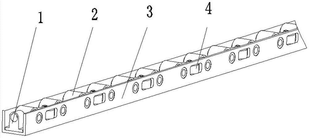
[0027] The invention provides an installation support rail for an underwater vehicle battery pack, see attached figure 1 , including: positioning hole seat 1, support wheel 2, installation base 3, guide wheel 4 and bushing 19;

[0028] See attached figure 2 , the installation base 3 is a U-shaped strip structure, and evenly distributed square holes and round holes are respectively opened on the two side plates of the U-shaped strip structure; the material of the installation base 3 is selected from high-strength aluminum profiles , its high-strength characteristics enable the entire track to maintain good rigidity in a state of light weight and small size, and due to the serialization and standardization of aluminum profiles, the track has the advantages of simple structure, low cost, and good processing technology;

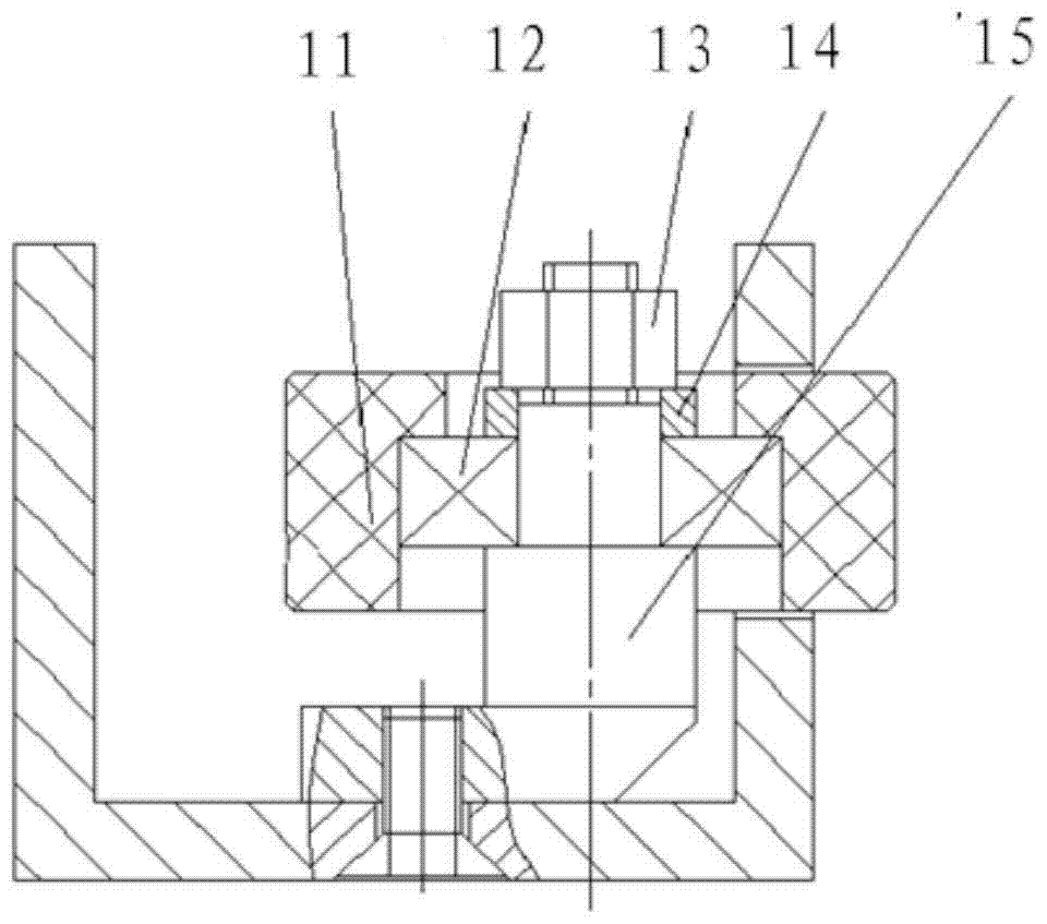
[0029] See attached image 3 , the...


PUM


Abstract

The invention discloses an installation and support rail for an underwater vehicle battery pack, which belongs to the technical field of underwater robots; it includes: a positioning hole seat, a support wheel, an installation base and a guide wheel; The two ends of the base plate; the two ends of the central axis of the support wheel are installed in the round holes of the two side plates of the installation base; the central axis of the guide wheel is fixed on the bottom plate of the installation base, wherein the outer peripheral surface of the guide wheel passes through Located in the same side hole of the installation base; the support wheels and guide wheels are arranged at intervals; the axis of the guide wheels is perpendicular to the bottom plate of the installation base, and the axis of the support wheels is perpendicular to the side plate of the installation base; the support wheels form the battery pack , Out of the running track of the shell of the underwater vehicle; the guide wheel is used to guide the unbiased movement of the battery pack; the track has good friction characteristics and high guiding precision, and the battery pack can be driven into and out of the water without bias by manpower aircraft hull.

Description

technical field [0001] The invention belongs to the technical field of underwater robots, and in particular relates to an installation support rail for a battery pack of an underwater vehicle. Background technique [0002] Autonomous underwater vehicles mostly use lithium batteries as energy sources, which puts forward higher requirements on energy use for medium and large underwater vehicles; lithium battery packs that provide large capacity, high power, and large-scale groups are used , as a special platform for loading and unloading and supporting battery packs in the form of rails, it is widely used on underwater vehicles. The current underwater vehicles directly use angle steel or angle aluminum as the installation and support rails of the battery pack. On the one hand, due to sliding friction, the running resistance of the battery pack into and out of the shell is large, and it is difficult to drive the battery pack by manpower alone. This requires design The special ...

Claims


Application Information

Patent Timeline
Patent Type & Authority Patents(China)
IPC IPC(8): H01M2/10H01M50/249H01M50/264
CPCH01M2220/20H01M50/20Y02E60/10
Inventor 金碧霞刘成胜詹传明方勇
Owner 710TH RES INST OF CHINA SHIPBUILDING IND CORP
Why Eureka
Try Eureka