Miniature electromagnetic relay

An electromagnetic relay, a small technology, applied in electromagnetic relays, electromagnetic relay details, relays and other directions, can solve the problems of high reliability, low cost, high withstand voltage requirements, to expand the use market, good isolation, increase creepage effect of distance

Active Publication Date: 2016-03-30
NINGBO FORWARD RELAY CORP
View PDF6 Cites 2 Cited by
  • Summary
  • Abstract
  • Description
  • Claims
  • Application Information

AI Technical Summary

Problems solved by technology

[0002] The relay is a widely used electronic component, which is used in household appliances, automobiles, industrial control, power systems, communication devices and other fields. The technical performance indicators of the relay have dielectric withstand voltage requirements, especially between the input end and the output end. The dielectric withstand voltage requirement is high, and the method of increasing the distance between the input end and the output end is usually used to increase the creepage distance between the input end and the output end and improve the dielectric withstand voltage between the input end and the output end, but this will cause The size of the relay increases, and the development of the whole machine using the relay requires the relay to be small in size, high in sensitivity, good in insulation performance, high in reliability and low in cost

Method used


Image

  • Miniature electromagnetic relay
  • Miniature electromagnetic relay
  • Miniature electromagnetic relay

Examples


Embodiment 1

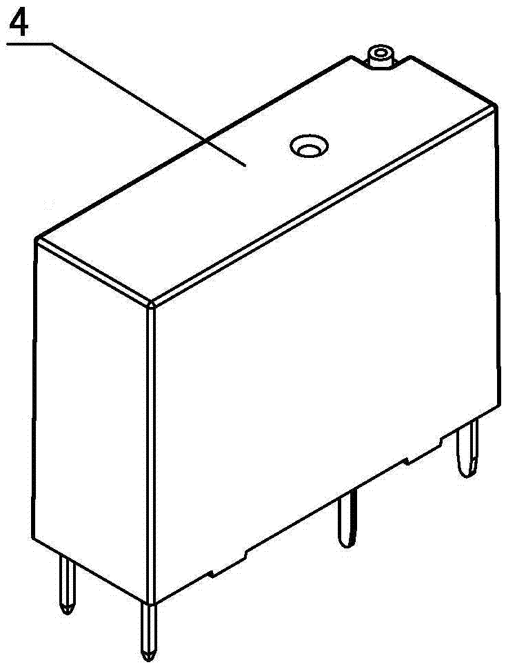
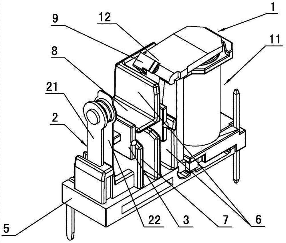
[0031]As shown in the figure, a small electromagnetic relay includes a magnetic circuit system 1, a contact system 2, a push block 3, a cover 4, and a base 5. The magnetic circuit system 1 includes an electromagnetic system 11 and an armature 12. The electromagnetic system 11 includes an iron Core 111, yoke 112, contact system 2 includes static contact group 21 and dynamic contact group 22, base 5 includes relay magnetic circuit system installation part 51, contact system installation part 52, electromagnetic system 11 and contact system 2 are arranged There is a first partition wall 6, and the first partition wall 6 is provided with a first push block chute 62 for installing the push block 3, and one end of the first partition wall 6 is integrally provided with an isolation bend extending toward the magnetic circuit system installation part 51. The folding part 61, the notch of the first pushing block slide groove 62 is arranged on the other end of the first partition wall 6, ...

Embodiment 2

[0034] The technical features are the same as those of the first embodiment, except that the second rib 42 is not integrally provided on the top wall of the casing 4 .

[0035] In the above embodiment, on the relay assembly line, when the parts and components of the relay are assembled with the base 5, Such as Figure 13 As shown, under the condition that the primary positioning of the base 5 remains unchanged, the pushing block 3, the dynamic contact group 22, the static contact group 21, the electromagnetic system 11, and the armature 12 are installed in the base 5 in sequence on the same axial direction. , simplifies the assembly on the production line of the relay, it is very convenient to operate, and it is easy to realize the automatic production of the relay, which greatly improves the efficiency of the production of the relay; The technical performance parameters of the assembled electromagnetic relay can be well controlled, so that the pass-through rate of the elect...


PUM


Abstract

The invention discloses a miniature electromagnetic relay, comprising a magnetic circuit system, a contact system, a push block, a shell and a base, wherein the magnetic circuit system comprises an electromagnetic system and an armature, the electromagnetic system comprises an iron core and a yoke, the contact system comprises a static contact group and a movable contact group, the base comprises a magnetic circuit system mounting part and a contact system mounting part of the relay, a first installation wall is arranged between the electromagnetic system and the contact system, a first push block chute used for mounting the push block is arranged on the first installation wall, wherein the push block comprises a body part, and a first flange part and a second flange part, which are arranged at both ends of the body part, a first boss connected with the armature is arranged on the outer end face of the first flange part, and a second boss connected with the movable contact group is arranged on the outer end face of the second flange part; the miniature electromagnetic relay has the advantages that the relay is simple and convenient to assemble, automatic production is liable to realize, the manufacturing cost is low, the volume is small, the insulating property is good, the application range is wide and the work is more reliable.

Description

technical field [0001] The invention relates to a relay, in particular to a small electromagnetic relay. Background technique [0002] The relay is a widely used electronic component, which is used in household appliances, automobiles, industrial control, power systems, communication devices and other fields. The technical performance indicators of the relay have dielectric withstand voltage requirements, especially between the input end and the output end. The dielectric withstand voltage requirement is high, and the method of increasing the distance between the input end and the output end is usually used to increase the creepage distance between the input end and the output end and improve the dielectric withstand voltage between the input end and the output end, but this will cause The size of the relay increases, and the development of the whole machine using the relay requires the relay to be small in size, high in sensitivity, good in insulation performance, high in r...

Claims


Application Information

Patent Timeline
IPC IPC(8): H01H50/04H01H50/64
CPCH01H50/042H01H50/64
Inventor 杨晓厦胡全伟王水君
Owner NINGBO FORWARD RELAY CORP
Why Eureka
Try Eureka