Spring energy storing device

A technology of energy storage device and support seat, which is applied to the power device, transformer and electrical components inside the switch, which can solve the problems of unstable movement, high acceleration and poor reliability, and achieve stable transmission, extended service life and gear meshing gentle effect

Active Publication Date: 2016-03-30
湖南德沃普电气股份有限公司
View PDF6 Cites 4 Cited by
  • Summary
  • Abstract
  • Description
  • Claims
  • Application Information

AI Technical Summary

Problems solved by technology

It solves the problems of large acceleration, unstable movement, low precision and poor reliability in the meshing process of the tap changer transmission mechanism of the existing on-load capacity-adjusting and voltage-regulating transformer.

Method used


Image

  • Spring energy storing device
  • Spring energy storing device
  • Spring energy storing device

Examples


Embodiment 1

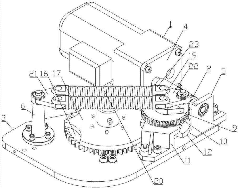
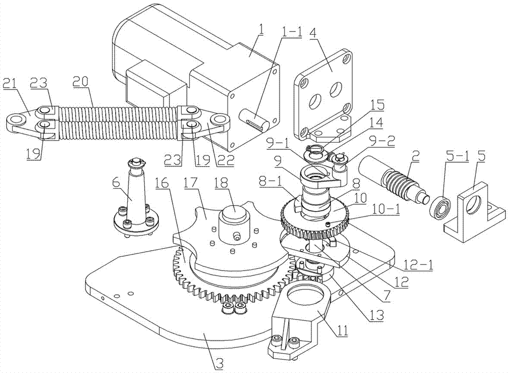
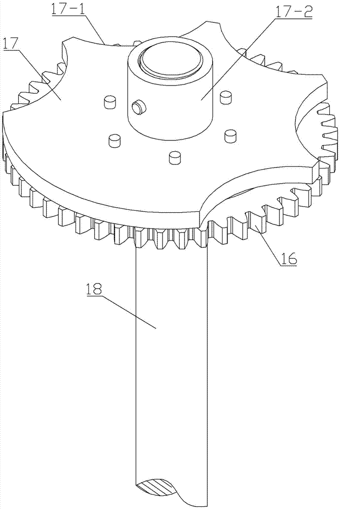
[0028] Spring energy storage device, including motor 1, worm 2, bottom plate 3, motor seat 4, worm support seat 5, tension spring mounting seat 6, main shaft 7, transfer sleeve 8, eccentric sleeve 9, worm wheel 10, support seat 11, cam lock Arc stop 12, incomplete gear 13, complete gear 16, concave wheel locking arc 17, output shaft 18, spring fixed shaft 19, extension spring 20, left connecting plate 21, right connecting plate 22 and deck 23.

[0029] The bottom plate 3 is provided with an output shaft hole 3-1. The lower end of the main shaft 7 is provided with a limiting boss 7-1. On the outer wall of one end of the transmission sleeve 8 is provided a projection 8-1 for pushing the cam locking arc 11 to rotate. An extension arm 9-1 is arranged on the outer wall of the eccentric sleeve 9, and a connecting column 9-2 is arranged at the end of the extension arm 9-1. The upper end surface of the worm wheel 10 is provided with a power transmission member 10 - 1 for driving the...


PUM


Abstract

A spring energy storing device, comprising a motor, a worm, a base plate, a motor base, a worm support base, a tension spring installation base, a main shaft, a transmission sleeve, an eccentric sleeve, a worm wheel, a support base, a cam locking arc, an incomplete gear, a complete wheel, a concave wheel locking arc, an output shaft, a spring fixing shaft, a tension spring, a left connecting plate, a right connecting plate and a clamping base. The invention is advantaged by that the transmission is accurate, the corotation and reversal angles of the output shaft are determined, corotation or reversal is terminated by embedding the cam locking arc in the arched gap of the concave wheel locking arc so as to resist against the concave wheel locking arc; the starting position of corotation (reversal) is the movement termination position of last time corotation (reversal); because the radian of the arched gap will not change, the cam locking arc will resist against the arched gap at the same position when corotation and reversal are terminated; therefore the corotation and reversal angles of the concave wheel locking arc are fixed.

Description

technical field [0001] The invention relates to an on-load capacity-regulating voltage-regulating transformer component, in particular a spring energy storage device used in conjunction with an on-load capacity-regulating voltage-regulating transformer, which is used to realize capacity-regulating and voltage-regulating tap changer And switching between star-delta connections. Background technique [0002] Most of the tap changer transmission mechanisms of the existing on-load capacity regulating and voltage regulating transformers are sheave spring energy storage devices, which include a sheave mechanism, a spring energy storage mechanism and a frame. When the spring energy storage mechanism releases energy instantaneously, A large impact is generated, so that the sheave has angular acceleration at the beginning and end of the indexing, and the impact generated by the instantaneous release of the spring energy storage mechanism is intensified with the increase of the sheave...

Claims


Application Information

Patent Timeline
Patent Type & Authority Applications(China)
IPC IPC(8): H01H3/30H01H3/40H01H3/42H01F29/04
CPCH01F29/04H01H3/30H01H3/40H01H3/42
Inventor 魏达王继忠刘平平
Owner 湖南德沃普电气股份有限公司
Why Eureka
Try Eureka