
Display device and current protection method thereof

A current protection and display device technology, applied to static indicators, instruments, etc., can solve the problem of signal line burnout of the display panel, and achieve the effect of avoiding excessive current

Active Publication Date: 2018-06-29
XIAMEN TIANMA MICRO ELECTRONICS +1
View PDF7 Cites 0 Cited by
  • Summary
  • Abstract
  • Description
  • Claims
  • Application Information

AI Technical Summary

Problems solved by technology

[0004] In view of this, the present invention provides a display device and its current protection method, so as to avoid problems such as burning of the driver chip and the signal line of the display panel caused by the excessive current generated by the voltage signal output by the integrated control circuit.

Method used


Image

  • Display device and current protection method thereof
  • Display device and current protection method thereof
  • Display device and current protection method thereof

Examples


Embodiment Construction

[0026] The following will clearly and completely describe the technical solutions in the embodiments of the present invention with reference to the accompanying drawings in the embodiments of the present invention. Obviously, the described embodiments are only some of the embodiments of the present invention, not all of them. Based on the embodiments of the present invention, all other embodiments obtained by persons of ordinary skill in the art without making creative efforts belong to the protection scope of the present invention.

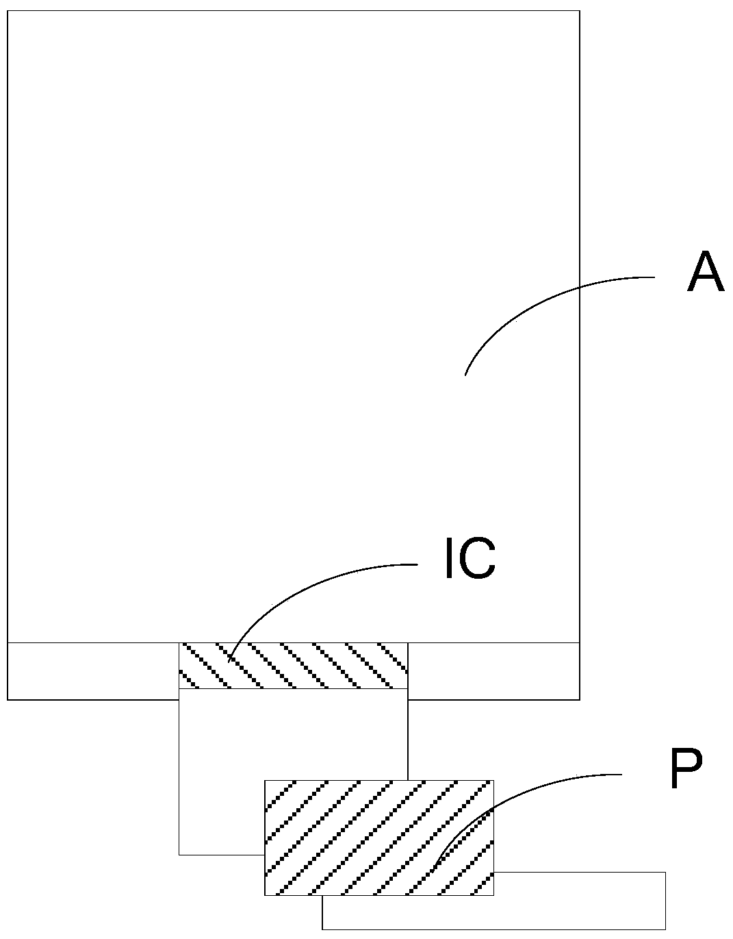
[0027] An embodiment of the present invention provides a display device, such as figure 1 As shown, the display device includes a display panel A, a driver chip IC, an integrated control circuit P, and a current protection circuit (not shown) between the driver chip IC and the integrated control circuit P. Wherein, the integrated control circuit P may be a flexible circuit board of the display device, or may be a circuit structure located on the ...


PUM


Abstract

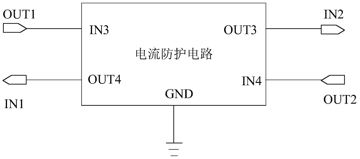
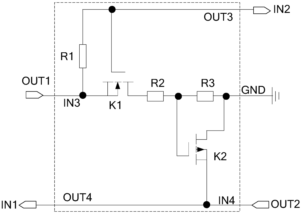
The invention provides a display device and a current protection method therefor. The device comprises a drive chip, an integrated control circuit, and a current protection circuit located between the drive chip and the integrated control circuit. The current protection circuit is used for controlling a drive control signal outputted by the drive chip to be outputted to a grounding end through a second drive control signal output end and a third drive control signal input end when a current generated by a voltage signal outputted by the integrated control circuit is greater than or equal to a threshold current, so as to enable the integrated control circuit to reset, and to stop the voltage signal, thereby preventing the voltage signal outputted by the integrated control circuit from generating an excessively large current so as to protect the drive chip and the signal lines of the display panel from being burnt up.

Description

technical field [0001] The invention relates to the technical field of liquid crystal display, and more specifically, to a display device and a current protection method thereof. Background technique [0002] Existing display devices include a display panel, a driver chip IC, and an integrated control circuit P, wherein the integrated control circuit P can control the normal display of the display panel after being connected to the display panel and powered on; the driver chip IC passes COG (Chip OnGlass, The chip is directly bound on the glass) and the process is bound on the display panel, which realizes the electrical connection between the display panel and the driver chip IC, so that the display panel can be driven by the driver chip IC for image display. In addition, the integrated control circuit P is also bound to the display panel through the COG process, so as to realize the electrical connection between the integrated control circuit P, the display panel and the d...

Claims


Application Information

Patent Timeline
Patent Type & Authority Patents(China)
IPC IPC(8): G09G3/36
CPCG09G3/36
Inventor 黄敏杨康鹏许育民
Owner XIAMEN TIANMA MICRO ELECTRONICS
Learn More