
Intelligent manufacturing router with cable interface protection function

A technology of interface protection and intelligent manufacturing, which is applied in the field of network technology, can solve problems such as cable shedding, electrical components burning, and circuit board carbonization, and achieve the effects of preventing the USB interface from loosening, reducing the overall center of gravity, and improving heat dissipation

Active Publication Date: 2021-08-24
江西山水光电科技股份有限公司
View PDF6 Cites 0 Cited by
  • Summary
  • Abstract
  • Description
  • Claims
  • Application Information

AI Technical Summary

Problems solved by technology

[0003] When the router is in use, in order to facilitate movement, a long section of network cable is generally reserved at the USB interface. Most of the existing routers lack a fixed structure for the network cable, so that the USB interface is easy to loose when the network cable shakes, causing the cable to fall off and the USB interface to contact. In addition, the existing routers have poor heat dissipation and dustproof effects. If the internal temperature is too high, the electrical components will be unstable, the circuit board will be carbonized, and the service life of the router will be reduced, and dust will easily enter the vacant USB interface. Excessive internal dust may cause short circuits and burn electrical components, etc.
[0004] In order to solve the above problems, the inventor provides an intelligent manufacturing router with a cable interface protection function, equipped with a cable fixing device, which can effectively prevent the cable from falling off and the USB interface from loosening, and has the advantages of good heat dissipation and dust resistance

Method used


Image

  • Intelligent manufacturing router with cable interface protection function
  • Intelligent manufacturing router with cable interface protection function
  • Intelligent manufacturing router with cable interface protection function

Examples


Embodiment Construction

[0026] The following will clearly and completely describe the technical solutions in the embodiments of the present invention with reference to the accompanying drawings in the embodiments of the present invention. Obviously, the described embodiments are only some, not all, embodiments of the present invention. Based on the embodiments of the present invention, all other embodiments obtained by persons of ordinary skill in the art without making creative efforts belong to the protection scope of the present invention.

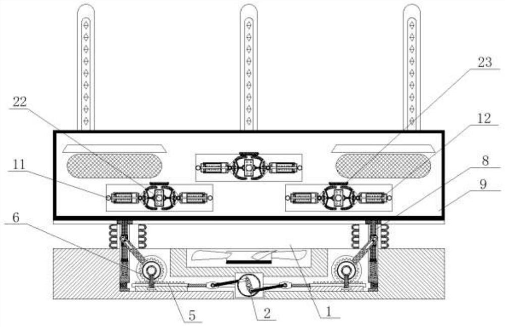
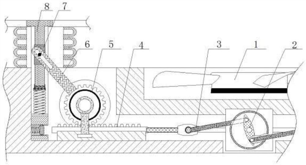
[0027] see Figure 1-6 , an intelligent manufacturing router with a cable interface protection function, comprising a cooling fan 1, a knob 2 is movably connected to the bottom of the cooling fan 1, a connecting rod 3 is movably connected to the left side of the above-mentioned knob 2, and the connecting rod 3 is provided with left and right two group, and the inner end of the connecting rod 3 is hinged on the knob 2, the outer end is movably connected with th...


PUM


Abstract

The invention relates to the technical field of network science and technology, and discloses an intelligent manufacturing router with a cable interface protection function, the intelligent manufacturing router comprises a cooling fan, the lower part of the cooling fan is movably connected with a knob, the left side of the knob is movably connected with a connecting rod, after a cable is inserted into a USB interface, a pull ring is loosened, the pull rod, the movable frame and the abutting blocks move towards the inner side, the abutting blocks on the two sides fix the cable from the two sides, the cable is prevented from falling off, meanwhile, the pressing springs and the hinge rods on the two sides drive the pressing rods to fix the USB interface, the situation that the USB interface is loosened, and consequently the network cable is in poor contact, through cooperation of a rotary knob, a connecting rod, a toothed plate, a transmission gear, an inclined rod, a connecting block and a lifting shaft, the router is pushed to integrally ascend, the heat dissipation capability of the router is improved, through cooperation of an abutting block, an over-buffer plate and a positioning spring, the problem that a cable is damaged due to the fact that the abutting block is too tight is effectively prevented, and the practicability of the device is further improved.

Description

technical field [0001] The invention relates to the technical field of network technology, in particular to an intelligent manufacturing router with a cable interface protection function. Background technique [0002] A router is a hardware device that connects two or more networks. It acts as a gateway between networks. It is a dedicated intelligent network device that reads the address in each data packet and then decides how to transmit it. [0003] When the router is in use, in order to facilitate movement, a long section of network cable is generally reserved at the USB interface. Most of the existing routers lack a fixed structure for the network cable, so that the USB interface is easy to loose when the network cable shakes, causing the cable to fall off and the USB interface to contact. In addition, the existing routers have poor heat dissipation and dustproof effects. If the internal temperature is too high, the electrical components will be unstable, the circuit bo...

Claims


Application Information

Patent Timeline
Patent Type & Authority Applications(China)
IPC IPC(8): H04Q1/02H04Q1/04H04L12/771H01R13/52H01R13/639H05K7/20H04L45/60
CPCH04Q1/035H04Q1/02H04Q1/04H04Q1/11H04L45/60H01R13/5213H01R13/639H05K7/20136
Inventor 茹丽娟
Owner 江西山水光电科技股份有限公司
Learn More