Machining process for sealing ring mold

A mold processing and sealing ring technology, applied in the field of sealing rings, can solve the problems of oversize, unilateral mold tearing groove, mold scrapping, etc., to achieve the effect of facilitating sanding, ensuring bottom size, and improving quality and accuracy

Active Publication Date: 2016-03-30
安徽宁国中鼎模具制造有限公司
View PDF5 Cites 11 Cited by
  • Summary
  • Abstract
  • Description
  • Claims
  • Application Information

AI Technical Summary

Problems solved by technology

It is easy to cause the mold to tear one side of the groove, and the size is out of tolerance, causing the mold to be scrapped

Method used


Image

  • Machining process for sealing ring mold

Examples


Embodiment Construction

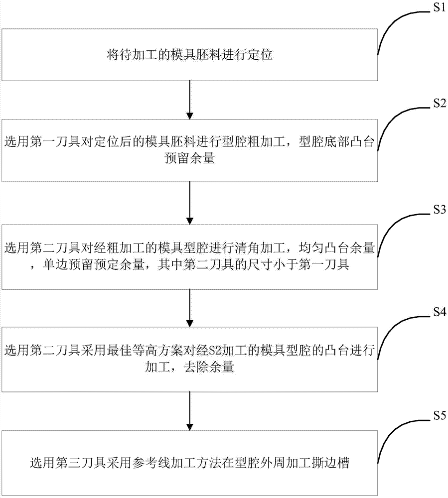
[0018] Such as figure 1 as shown, figure 1 It is a schematic flow chart of a sealing ring mold processing technology proposed by the present invention.

[0019] refer to figure 1 , a kind of sealing ring mold processing technology that the present invention proposes, comprises the following steps:

[0020] S1. Position the mold blank to be processed;

[0021] S2. Select the first tool to rough the mold cavity after positioning, and reserve a margin for the boss at the bottom of the cavity;

[0022] S3. Select the second tool to perform corner-clearing processing on the rough-processed mold cavity, uniform boss margin, and reserve a predetermined margin on one side, wherein the size of the second tool is smaller than the first tool, and the predetermined margin is 0.01-0.02mm, preferably, the predetermined margin is 0.015mm;

[0023] S4. Select the second tool and use the best contour plan to process the mold cavity boss processed by S2 from the middle of the cavity to rem...


PUM


Abstract

The invention discloses a machining process for a sealing ring mold. In the machining course, firstly, a large cutter is adopted for rough machining a mold cavity; then a small cutter is selected and used, and a plurality of balances are cleared away through clearance angle machining to make the balances on a boss even; and finally a small cutter is selected and used, a best equal-height scheme is adopted for overall machining in place started from the middle, the bottom size is ensured, and cutter lapping defects are reduced; in addition, a torn edge groove is machined through a layering machining method, so that a machined single side of the torn edge groove is avoided, and the quality and precision of the torn edge groove are improved. The optimally designed machining process for the sealing ring mold is simple in process and reasonable in design. After overall machining is adopted for the boss at the bottom of the cavity, the cutter lapping defects in the cavity are lifted, so that sanding is convenient, and the work efficiency is improved. The machining precision of the mold is greatly improved, and scrapping of the mold is avoided.

Description

technical field [0001] The invention relates to the technical field of sealing rings, in particular to a mold processing technology for sealing rings. Background technique [0002] In the traditional sealing ring mold processing technology, multiple knives are used to clean the corners of the bottom bosses of the upper and lower mold cavities, and they are directly processed to the required size. In actual processing, tool mark joints are easy to occur, and the position is at the bottom of the cavity. Due to the small size of the bottom of the cavity of this type of mold, it is not easy to sand, resulting in a decline in product quality. Reduced work efficiency. When processing the tearing edge groove, use more than one knife to process to the end, without changing the knife. It is easy to cause the mold to tear one side of the groove, the size is out of tolerance, and the mold is scrapped. Contents of the invention [0003] In order to solve the technical problems exis...

Claims


Application Information

Patent Timeline
Patent Type & Authority Applications(China)
IPC IPC(8): B23P15/24
CPCB23P15/24
Inventor 陈成
Owner 安徽宁国中鼎模具制造有限公司
Why Eureka
Try Eureka