


Quick Research
Generate reliable direction feasibility study reports for your R&D in just a few steps.

Technical Q&A
Discover and master advanced knowledge NOW. Basics, ideas, possibilities, all at once.

Find Solutions
As an expert in R&D theories, this can generate solutions to your technical problems instantly.

Evaluate Feasibility
Analyze your overall solution with one click, know your potential R&D risks in advance.

Monitor Landscape
Get weekly tech updates, stay abreast of the latest tech innovations and key insights.
Mineral separation breaking device
A crushing device and crushing technology, which is applied in the direction of grain processing, etc., can solve the problems of poor quality of crushed materials, thin thickness, and great influence on the quality of finished mineral materials, and achieve high-quality crushed materials, sufficient crushing, and scientific design. Effect
- Summary
- Abstract
- Description
- Claims
- Application Information
AI Technical Summary
Problems solved by technology
Method used
Image

Examples
Embodiment 1
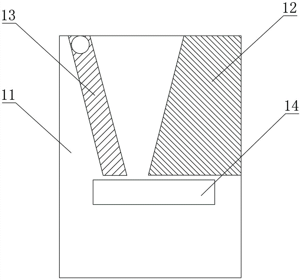
[0025] Such as figure 1 As shown, a crushing device for mineral processing includes a box body 11, a movable jaw plate 13 and a static jaw plate 12. A plurality of transmission rollers 14 are installed at the same place, and the rotation directions of the plurality of transmission rollers 14 are consistent. The plurality of transmission rollers 14, the lower end of the static jaw plate 12 and the lower end of the movable jaw plate 13 form a fence type As for the screening net, the box body 11 is provided with residual material outlets corresponding to the conveying directions of the plurality of conveying rollers 14 . A plurality of the conveying rollers 14 form a slope along the conveying direction. The endmost conveying roller 14 along the conveying direction is higher than the conveying roller 14 adjacent to it to form a stop step.
[0026] Working principle: Mineral material enters the crushing chamber for crushing. If flat mineral material enters and is not crushed by t...
Embodiment 2
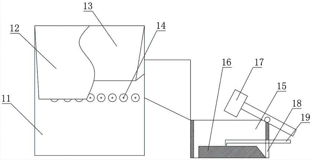
[0028] Such as figure 2 As shown, the residual material outlet includes an inclined material guide plate with one end connected to the discharge ends of a plurality of the conveying rollers 14, baffles on both sides of the material guide plate and a baffle connected to the lower end of the material guide plate. Residue warehouse 15. It also includes a residual material crushing device, which includes a crushing table 16 arranged at the bottom of the residual material bin 15 and a crushing hammer 17 corresponding to the crushing table 16 . Each side wall of the residual material bin 15 is respectively provided with push plates, and each of the push plates is driven by a motor and a cam transmission mechanism to perform consistent reciprocating motions. A scraper 19 is arranged on the crushing table 16, and a discharge port 18 is arranged at the bottom of the side of the waste bin. The transmission roller 14 is covered with an anti-skid rubber washer. The hammer head portion...
PUM
 Abstract
Description
Claims
Application Information
 - R&D Engineer
- R&D Manager
- IP Professional
- Industry Leading Data Capabilities
- Powerful AI technology
- Patent DNA Extraction
Browse by: Latest US Patents, China's latest patents, Technical Efficacy Thesaurus, Application Domain, Technology Topic, Popular Technical Reports.
© 2024 PatSnap. All rights reserved.Legal|Privacy policy|Modern Slavery Act Transparency Statement|Sitemap|About US| Contact US: help@patsnap.com