
Surface-wave plasma equipment

A plasma and surface wave technology, applied in the direction of plasma and electrical components, can solve the problems of poor plasma uniformity, different density distribution, poor process quality, etc., and achieve the effect of improving process quality

Inactive Publication Date: 2016-03-23
BEIJING NAURA MICROELECTRONICS EQUIP CO LTD
View PDF9 Cites 27 Cited by
  • Summary
  • Abstract
  • Description
  • Claims
  • Application Information

AI Technical Summary

Problems solved by technology

[0003] However, the density distribution of the surface wave plasma generated by the existing surface wave plasma equipment is constant. Under different process conditions (for example, pressure, process gas type), the density distribution of the plasma diffused to the substrate S will vary. different, which can result in poor uniformity of the plasma over a large area of ​​the wafer under different process conditions, resulting in poor process quality

Method used


Image

  • Surface-wave plasma equipment
  • Surface-wave plasma equipment
  • Surface-wave plasma equipment

Examples


Embodiment Construction

[0024] In order for those skilled in the art to better understand the technical solution of the present invention, the surface wave plasma device provided by the embodiment of the present invention will be described in detail below with reference to the accompanying drawings.

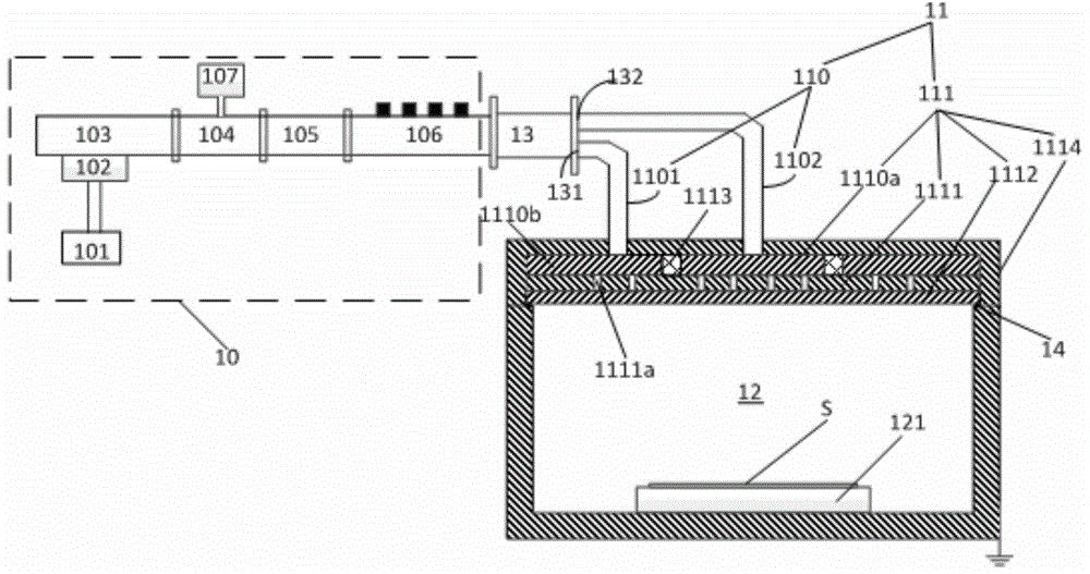
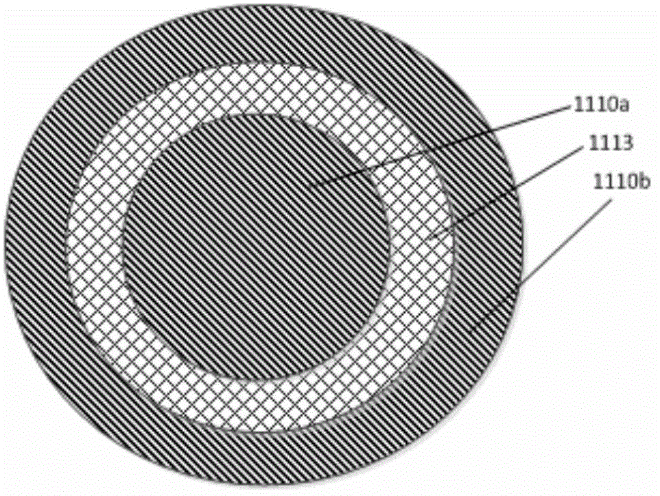
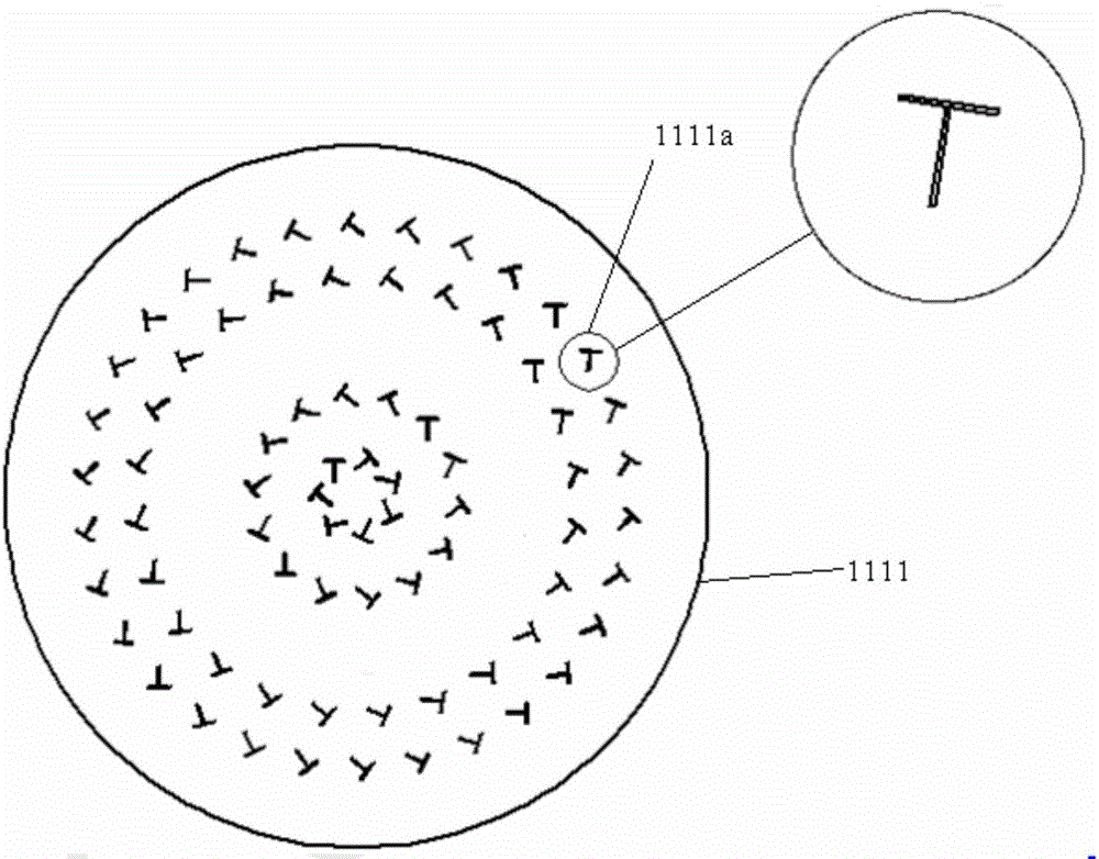
[0025] figure 1 Schematic diagram of the structure of the surface wave plasma device provided by the embodiment of the present invention. figure 2 for figure 1 Top view of the stagnant wave plate shown in . image 3 for figure 1 Top view of the slit plate shown in . Please also refer to Figure 1-Figure 3 , the surface wave plasma equipment provided in this embodiment includes a microwave generating device 10 , a microwave transmission device 11 and a reaction chamber 12 connected in sequence. Wherein, the microwave generating device 10 is used to generate microwaves forming surface wave plasma; the microwave transmission device 11 includes a waveguide 110 and a microwave antenna 111, and the micr...


PUM


Abstract

The invention provides surface wave plasma equipment. The surface wave plasma equipment comprises a microwave generation device, a microwave transmission device and a reaction cavity which are successively connected; the microwave generation device is used to generate a microwave forming a surface-wave plasma; the microwave transmission device comprises wave guides and a microwave antenna, the microwave antenna is divided into a plurality of sub antennas, the sub antennas correspond to different areas of the reaction cavity, the number of the wave guides is equal to the number of the sub antennas, the wave guides are correspondingly connected with the sub antennas one by one, and the microwave generated by the microwave generation device is coupled to the different areas of the reaction cavity via the wave guides and the sub antennas corresponding to the wave guides; and, through respective adjustments of power of the microwave coupled to the different areas of the reaction cavity, uniform and large-area surface-wave plasmas are formed over a substrate in the reaction cavity. According to the surface-wave plasma equipment provided by the invention, the uniform and large-area surface-wave plasmas can be formed over the substrate under different process conditions, and then process quality can be improved.

Description

technical field [0001] The invention belongs to the technical field of microelectronic processing, and in particular relates to a surface wave plasma device. Background technique [0002] Plasma equipment is widely used in the manufacturing process of integrated circuits or MEMS devices. Currently, plasma devices include capacitively coupled plasma devices, inductively coupled plasma devices, electron cyclotron resonance plasma devices, and surface wave plasma devices. Among them, capacitively coupled plasma equipment is easy to generate large-area uniformly distributed plasma, which is suitable for etching dielectric thin films; electron cyclotron resonance plasma equipment can obtain plasma with higher density at lower pressure, but it needs to introduce External magnetic field, so the cost is relatively high; compared with other plasma equipment, surface wave plasma equipment can obtain higher plasma density, lower electron temperature, and does not need to increase the ...

Claims


Application Information

Patent Timeline
IPC IPC(8): H05H1/46
Inventor 韦刚
Owner BEIJING NAURA MICROELECTRONICS EQUIP CO LTD
Learn More