Direct evaporative passive self-cooling deflector

A deflector and evaporative technology, applied in the field of direct evaporative passive self-cooling deflectors, can solve the problems of reduced radiation heat transfer intensity, air deflectors without heat capacity and heat export capacity, etc., to increase cooling ability, promote natural ventilation, and reduce the effect of system thermal resistance

Active Publication Date: 2019-12-13
CHINA NUCLEAR POWER ENG CO LTD
View PDF11 Cites 0 Cited by
  • Summary
  • Abstract
  • Description
  • Claims
  • Application Information

AI Technical Summary

Problems solved by technology

Traditional air deflectors do not have sufficient heat capacity and heat export capability. The heat is mainly carried away by surface air flow. When the radiation is strong, the deflector will heat up rapidly, reducing the intensity of radiation heat transfer and cannot be maintained at a high level.

Method used


Image

  • Direct evaporative passive self-cooling deflector
  • Direct evaporative passive self-cooling deflector
  • Direct evaporative passive self-cooling deflector

Examples


Embodiment Construction

[0033] The specific implementation manners of the present invention will be further described in detail below in conjunction with the accompanying drawings.

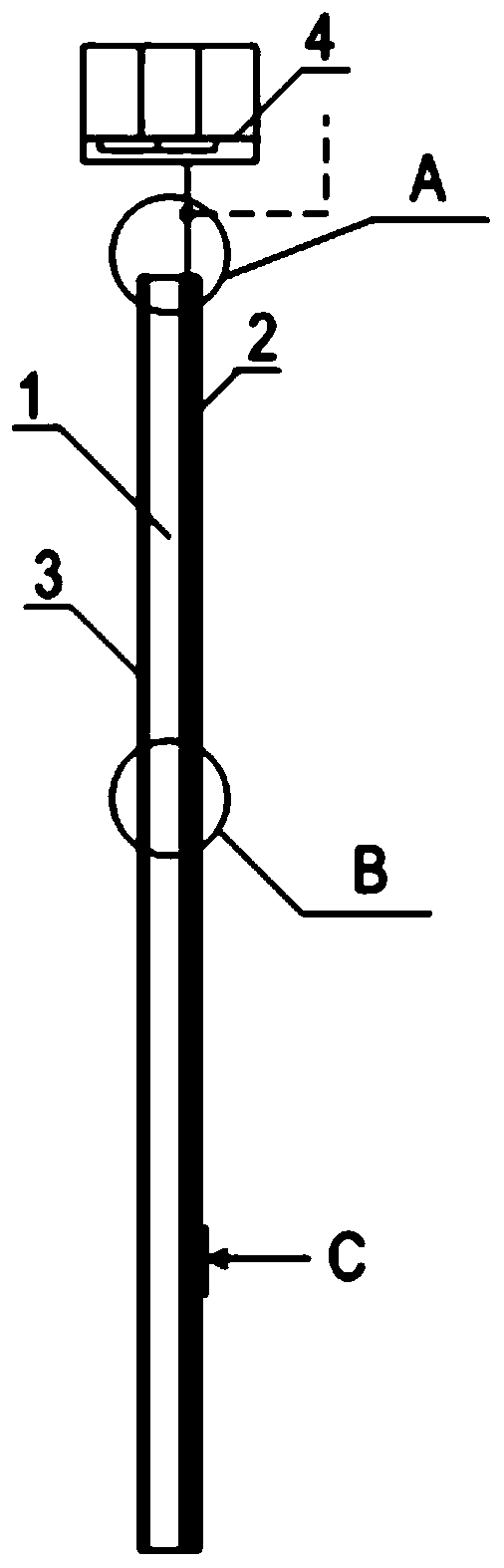
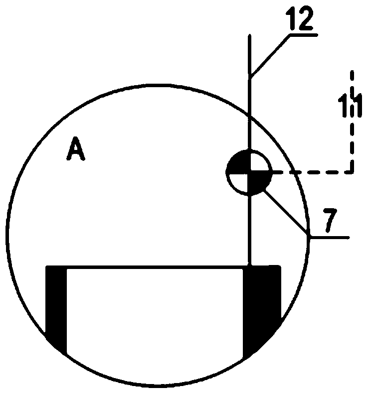
[0034] Such as Figure 1-3 Shown is a schematic structural view of the direct evaporative passive self-cooling deflector provided by the present invention. The deflector comprises a deflector structural skeleton 1 , one side of the deflector structural skeleton 1 is provided with a deflector porous material covering layer 2 , and the other side of the deflector structural skeleton 1 is covered with a deflector heat insulating layer 3 . A coolant channel 5 is provided on the frame 1 of the deflector structure, and the coolant channel 5 is a root-like structure, which is connected to the moisture-retaining coolant tank 4 of the deflector on the top of the containment through a coolant inlet pipeline 12 . The coolant channel 5 is provided with a coolant diffusion hole 6 for coolant distribution, and the coolant diffusion h...


PUM


Abstract

The invention relates to a direct evaporative passive self-cooling flow guide plate. The direct evaporative passive self-cooling flow guide plate is arranged in a cooling system of containment of a nuclear power plant and comprises a flow guide plate structural framework. A flow guide plate porous material cover layer is arranged on one side of the flow guide plate structural framework, a flow guide plate heat-insulation layer is arranged on the other side of the flow guide plate structural framework, a coolant channel is arranged on the flow guide plate structural framework and is connected with a flow guide plate moisture retention coolant water tank by a coolant access pipeline, the flow guide plate moisture retention coolant water tank is arranged on the top of the containment, and coolant diffusion holes are formed in the coolant channel and are communicated with the flow guide plate porous material cover layer. The direct evaporative passive self-cooling flow guide plate has the advantages that evaporative heat exchange mechanisms are added to the flow guide plate, temperature difference between air of descending sections and air in heated channels of ascending sections is increased, heat resistance of the system can be reduced, natural ventilation flow rates can be promoted, and accordingly the cooling capacity of the system can be improved.

Description

technical field [0001] The invention belongs to the field of cooling equipment, in particular to a direct evaporative passive self-cooling deflector. Background technique [0002] The traditional air deflectors in the containment cooling system of nuclear power plants use their sides to form air passages with the adjacent building surfaces to regulate air flow, thereby promoting the heat transfer process on the building surfaces. In the passive containment cooling system design of AP1000 third-generation nuclear power plant in the United States, the air deflector, the outer surface of the steel containment vessel and the inner surface of the concrete containment vessel constitute the reentrant air channel. According to theoretical calculations, this design can increase the heat exchange capacity of the system by more than 50%. The heat exchange in the ascending section of the reentrant channel is a heat-mass coupled dredging process. Using the technology of the present inve...

Claims


Application Information

Patent Timeline
Patent Type & Authority Patents(China)
IPC IPC(8): G21C15/18
CPCG21C15/18Y02E30/30
Inventor 韩旭封有才刘宇李军张丽元一单
Owner CHINA NUCLEAR POWER ENG CO LTD
Why Eureka
Try Eureka