
Airplane steering surface deflection angle measurement device and method

An angle measuring device and rudder surface deflection technology, which is applied in the direction of measuring devices, electrical devices, instruments, etc., can solve the problems of large workload and large errors in measuring the deflection angle of aircraft rudder surfaces, and achieves easy installation and operation and high precision. , easy to carry effect

Active Publication Date: 2016-03-23
CHINA ACAD OF AEROSPACE AERODYNAMICS
View PDF11 Cites 17 Cited by
  • Summary
  • Abstract
  • Description
  • Claims
  • Application Information

AI Technical Summary

Problems solved by technology

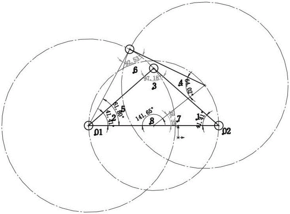
[0005] Another object of the present invention is to provide a device for measuring the deflection angle of the aircraft control surface. The present invention adopts a four-link structure, which skillfully solves the problems of large workload and large errors in the measurement of the aircraft control surface deflection angle.
[0006] Yet another object of the present invention is to provide a method for measuring the deflection angle of the aircraft rudder surface. The method of the present invention cleverly solves the problem of large workload and large errors in the measurement of the aircraft rudder surface deflection angle by adopting the principle of four-link structure. At the same time, it can solve the determination of the rudder surface rotation angle of each angle wing position in the range from the horizontal rudder surface to the vertical rudder surface

Method used


Image

  • Airplane steering surface deflection angle measurement device and method
  • Airplane steering surface deflection angle measurement device and method
  • Airplane steering surface deflection angle measurement device and method

Examples


Embodiment Construction

[0036] The present invention will be further described in detail below in conjunction with the accompanying drawings, so that those skilled in the art can implement it with reference to the description.

[0037] It should be understood that terms such as "having", "comprising" and "including" as used herein do not entail the presence or addition of one or more other elements or combinations thereof.

[0038] The aircraft rotating airfoil comprises a fixed side of the aircraft rotating airfoil and an aircraft control surface which can rotate around the fixed side of the aircraft rotating airfoil.

[0039] Such as figure 1 and figure 2 As shown, the present invention provides a kind of aircraft steering surface deflection angle measuring device, comprising:

[0040] First and second connecting rods, the first ends of the first and second connecting rods are respectively detachably pivoted to the fixed side of the aircraft rotating wing surface and the aircraft rudder surface ...


PUM


Abstract

The invention discloses an airplane steering surface deflection angle measurement device comprising first and second connecting rods, and first, second and third angle measurement devices. The first ends of the first and second connecting rods are detachably and pivotally connected with an airplane rotating wing surface fixed side and an airplane steering surface respectively in use. The second ends of the first and second connecting rods are pivotally connected with each other and are away from the airplane rotating wing surface in use. The first, second and third angle measurement devices are respectively arranged at the first end of the first connecting rod, the first end of the second connecting rod and the second end of the first connecting rod so as to respectively detect the angles of a first inclined angle formed by the first connecting rod and the airplane rotating wing surface fixed side, a second inclined angle formed by the second connecting rod and the airplane steering surface and the first inclined angle formed by the first connecting rod and the second connecting rod. The invention also discloses an airplane steering surface deflection angle measurement method. The steering surface rotating angles of all angle wing potions within range from a horizontal steering surface to a vertical steering surface can be measured.

Description

technical field [0001] The invention belongs to the technical field of measuring devices, and in particular relates to a device and method for measuring an aircraft rudder surface angle. Background technique [0002] The aircraft rotating airfoil comprises a fixed side of the aircraft rotating airfoil and an aircraft control surface which can rotate around the fixed side of the aircraft rotating airfoil. In the actual flight process, the error between the actual flip angle of the rudder surface and the set angle directly affects the flight attitude of the aircraft. The motion attitude of the aircraft plays a vital role. In recent years, with the continuous development of aircraft for various purposes, the workload of rudder surface angle measurement is increasing, and the measurement accuracy requirements are getting higher and higher, so the demand for measurement technology of rudder surface rotation angle is also increasing. [0003] At present, there are three commonly...

Claims


Application Information

Patent Timeline
Patent Type & Authority Applications(China)
IPC IPC(8): G01B7/30
CPCG01B7/30
Inventor 高华东于德洋盛晓亮扈亦越
Owner CHINA ACAD OF AEROSPACE AERODYNAMICS
Learn More