Waterproof button structure and mobile terminal device
A key and device technology, which is applied in the field of waterproof key structure design, can solve the problems that the structure is not tight, cannot meet the requirements of thin and light mobile phones, narrow edges, and large space occupied by waterproof keys.
- Summary
- Abstract
- Description
- Claims
- Application Information
AI Technical Summary
Problems solved by technology
Method used
Image
Examples
Embodiment 1
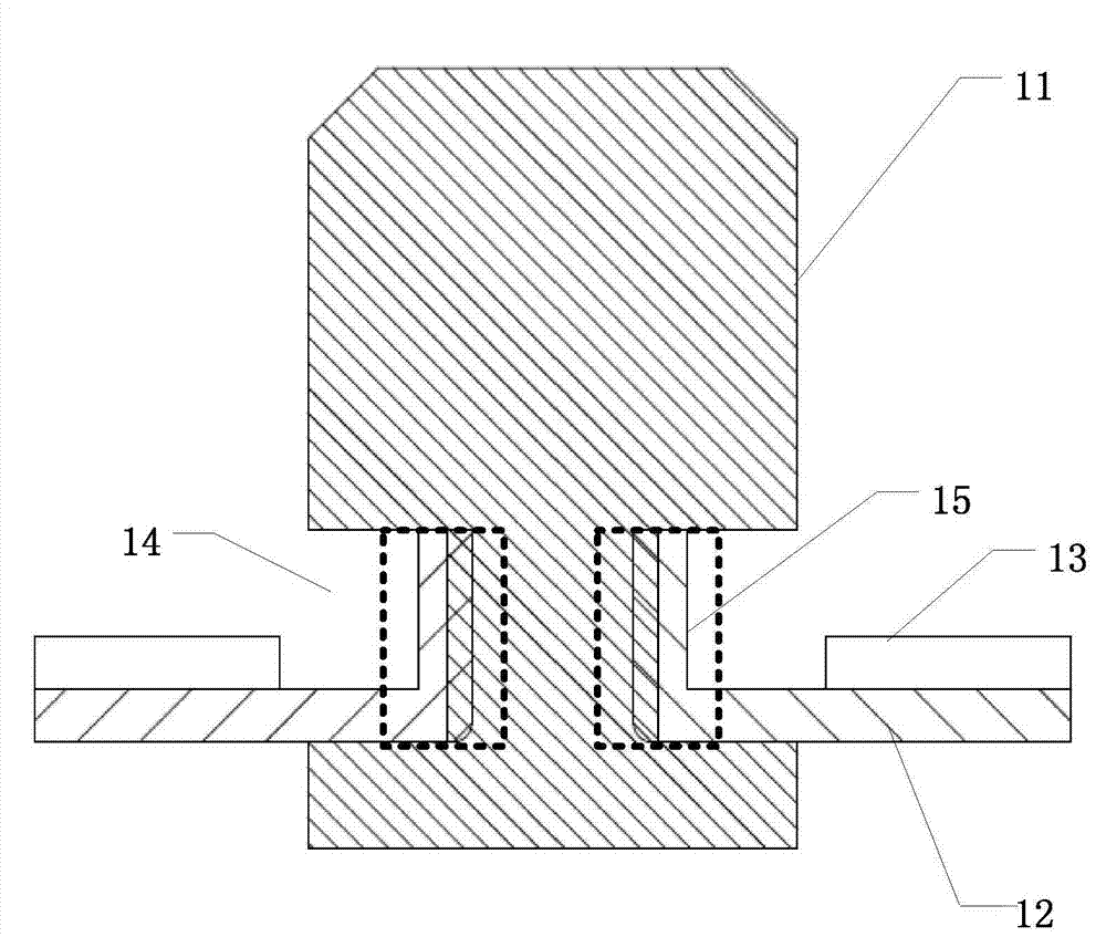
[0033] An embodiment of the present invention provides a waterproof button structure, figure 1 It is a top view of a waterproof button structure provided by Embodiment 1 of the present invention, figure 2 for along figure 1 The cross-sectional view of AA direction in the middle, image 3 for along figure 1 Cross-sectional view in the middle BB direction. see figure 2 , the waterproof key structure includes a keycap 11, a soft glue 12, and a bonding layer 13, wherein the side wall of the keycap 11 has a groove 14, and the center of the soft glue 12 has a through hole (not shown), There is an elastic wall 15 around the through hole, and the adhesive layer 13 is located on the edge of the upper surface of the soft rubber outside the elastic wall 15, and is used to stick the waterproof key structure to the device casing. The key cap 11 Through the soft glue through hole, the elastic wall 15 is in interference fit with the key cap groove 14 .
[0034] In order to facilitate...
Embodiment 2
[0041] The embodiment of the present invention is a further optimization of the first embodiment above, Figure 4 It is a top view of a waterproof button structure provided by Embodiment 2 of the present invention, Figure 5 for along Figure 4 The cross-sectional view of AA direction in the middle, Figure 6 for along Figure 4 Cross-sectional view in the middle BB direction. see Figure 5 , the waterproof key structure includes a key cap 21, a soft glue 22, and a bonding layer 23, wherein the side wall of the key cap 21 has a groove 24, and the center of the soft glue 22 has a through hole, and the surrounding of the through hole It has an elastic wall 25, the adhesive layer 23 is located on the edge of the upper surface of the soft rubber outside the elastic wall 25, and is used to stick the waterproof button structure to the device casing, and the keycap 21 runs through the soft rubber Through holes, the elastic wall 25 is in interference fit with the key cap groove 2...
Embodiment 3
[0045] The embodiment of the present invention is a further optimization of the second embodiment above, Figure 7 It is a top view of a waterproof button structure provided by Embodiment 3 of the present invention, Figure 8 for along Figure 7 The cross-sectional view of AA direction in the middle, Figure 9 for along Figure 7 Cross-sectional view in the middle BB direction. see Figure 8 , the waterproof key structure includes a key cap 31, a soft glue 32, and a bonding layer 33, wherein the side wall of the key cap 31 has a groove 34, and the center of the soft glue 32 has a through hole, and the surrounding of the through hole It has an elastic wall 35, the adhesive layer 33 is located on the edge of the upper surface of the soft rubber outside the elastic wall 35, and is used to stick the waterproof button structure to the device casing, and the keycap 31 runs through the soft rubber Through holes, the elastic wall 35 is in interference fit with the key cap groove ...
PUM
 Abstract
Description
Claims
Application Information
 - R&D
- Intellectual Property
- Life Sciences
- Materials
- Tech Scout
- Unparalleled Data Quality
- Higher Quality Content
- 60% Fewer Hallucinations
Browse by: Latest US Patents, China's latest patents, Technical Efficacy Thesaurus, Application Domain, Technology Topic, Popular Technical Reports.
© 2025 PatSnap. All rights reserved.Legal|Privacy policy|Modern Slavery Act Transparency Statement|Sitemap|About US| Contact US: help@patsnap.com


