
Valve mechanism system with hydraulic lash adjuster and exhaust brake

A lash adjuster, exhaust valve technology, applied in the direction of machine/engine, engine components, mechanical equipment, etc.

Active Publication Date: 2016-03-23
EATON SRL
View PDF5 Cites 11 Cited by
  • Summary
  • Abstract
  • Description
  • Claims
  • Application Information

AI Technical Summary

Problems solved by technology

In many cases, this clearance may not be compatible with typical hydraulic lash adjusters (HLAs)

Method used


Image

  • Valve mechanism system with hydraulic lash adjuster and exhaust brake
  • Valve mechanism system with hydraulic lash adjuster and exhaust brake
  • Valve mechanism system with hydraulic lash adjuster and exhaust brake

Examples


Embodiment Construction

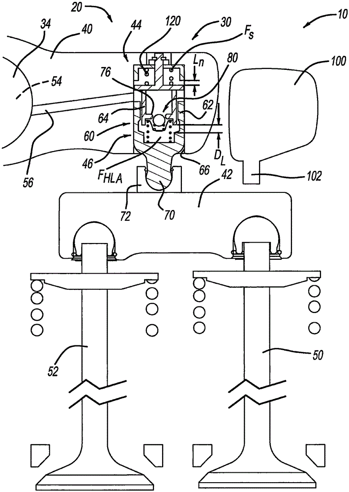
[0020] First refer to figure 1 , a portion of a valvetrain assembly constructed in accordance with an example of the present invention is shown and generally designated by the reference numeral 10 . Portions of the valvetrain assembly 10 use engine braking. Portion of valvetrain assembly 10 may include rocker arm assembly 20 having a series of intake rocker arm assemblies (not specifically shown) and a series of exhaust valve rocker arm assemblies 30 . Rocker shaft 34 is received by a rocker housing (not specifically shown). As will be understood from the discussion below, rocker shaft 34 cooperates with rocker assembly 20 and, more specifically, exhaust valve rocker assembly 30 to communicate oil to exhaust valve rocker assembly 30 during engine braking.

[0021] Now generally refer to Figure 1-5 Exhaust valve rocker arm assembly 30 may generally include a rocker arm 40 , a valve bridge 42 , an elastic pod 44 , and a hydraulic lash adjuster (HLA) assembly 46 . The valve ...


PUM


Abstract

The invention relates to a valve mechanism system with a hydraulic lash adjuster and an exhaust brake. In the brake mode of an engine, an operable exhaust valve rocker arm assembly comprises a rocker arm shaft, a rocker arm, a valve cross arm, a discharge valve, a hydraulic lash adjuster and an elastic tank box. The rocker arm shaft defines a pressurized oil supply pipeline. The rocker arm receives the rocker arm shaft and is configured to rotate about the rocker arm shaft. The rocker arm is provided with an oil supply passage defined therein. The valve cross arm is engaged with a first exhaust valve and a second exhaust valve. The discharge valve is provided with a piston capable of moving between a retractable position and an extendable position. The hydraulic lash adjuster assembly is arranged on the rocker arm and comprises a first plunger that moves between a first position and a second position. At the first position, the first plunger extends rigidly to be cooperatively engaged with the valve cross arm.

Description

[0001] Cross References to Related Applications [0002] This application claims priority to US Patent Application No. 62 / 017,321, filed June 26, 2014, and US Patent Application No. 62 / 024,633, filed July 15, 2014. The contents of the above patent applications are incorporated herein by reference. technical field [0003] The present invention relates generally to a rocker arm assembly for use in a valvetrain assembly having an exhaust brake, and more particularly to a rocker arm assembly having an integrated hydraulic capsule and hydraulic lash adjuster The rocker arm assembly of the rocker arm. Background technique [0004] Engine braking can be used to counteract the forces within the engine to eventually slow the vehicle down. In a typical valvetrain assembly used with engine brakes, the exhaust valves are actuated by rocker arms that engage the exhaust valves through valve bridges. The rocker arm swings in response to the cam on the rotating camshaft and presses down...

Claims


Application Information

Patent Timeline
Patent Type & Authority Applications(China)
IPC IPC(8): F01L1/18F01L1/24
Inventor N·安瑞森尼
Owner EATON SRL
Learn More