
Cooling flow path for stator vanes of turbine engine

A turbine engine and stator blade technology, applied in the direction of engine components, machines/engines, stators, etc., can solve the problems of easy high temperature thermal deformation, cracks, loss of function of stator blades, etc., to reduce processing costs, easy processing, simple structure Effect

Active Publication Date: 2016-03-23
CHINA HANGFA SOUTH IND CO LTD
View PDF5 Cites 4 Cited by
  • Summary
  • Abstract
  • Description
  • Claims
  • Application Information

AI Technical Summary

Problems solved by technology

[0004] The invention provides a cooling flow path for the stator blades of a turbine engine to solve the technical problem that the existing turbine stator blades are prone to high-temperature thermal deformation and even cracks during operation, thereby causing the function loss of the stator blades

Method used


Image

  • Cooling flow path for stator vanes of turbine engine
  • Cooling flow path for stator vanes of turbine engine
  • Cooling flow path for stator vanes of turbine engine

Examples


Embodiment Construction

[0025] The embodiments of the present invention will be described in detail below with reference to the accompanying drawings, but the present invention can be implemented in many different ways defined and covered by the claims.

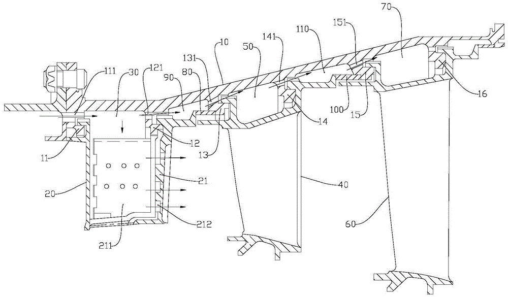
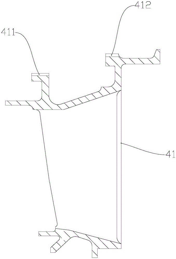
[0026] Such as figure 1 As shown, the preferred embodiment of the present invention provides a cooling flow path for the stator blades of a turbine engine. The turbine engine includes a turbine casing 10, and the inner wall of the turbine casing 10 is sequentially provided with a first support rib 11 for supporting the stator blades, a second The second support rib 12, the third support rib 13, the fourth support rib 14, the fifth support rib 15 and the sixth support rib 16, the first stage stator blade 20 is suspended between the first support rib 11 and the second support rib 12 It is surrounded by the turbine case 10 to form a first annular channel 30 , and the second-stage stator blade 40 is suspended between the third support rib 13 and the fou...


PUM


Abstract

The invention discloses a cooling flow path for stator vanes of a turbine engine. A first air hole, through which upstream cooling air is introduced in a first annular passage to cool a turbine engine casing and an upper edge plate of a first-stage stator vane, is formed in a first bearing rib. The first-stage stator vane comprises a plurality of first guiding vanes. An air chamber communicated with the first annular passage is formed in the body of each first-stage guiding vane, and is also communicated with a gas passage in the turbine engine casing so as to enable cooling air to be discharged in the gas passage after the first-stage guiding vanes are cooled with cooling air. The cooling flow path is simple in structure, the first-stage guiding vanes are not deformed or cracked in operation, the parts constituting the cooling flow path are easy to process, and the processing cost can be reduced; and in addition, the quantity of introduced cooling air is smaller, and the power of an engine is not remarkably reduced when a small amount of cooling air is mixed in high-temperature acting gas, so that the requirement on the using power of the engine can be ensured.

Description

technical field [0001] The invention relates to the field of aero-engines, in particular to a cooling flow path for a stator blade of a turbine engine. Background technique [0002] In a turboprop engine, the turbine includes rotor blades, stator blades and a turbine casing. The stator blades have three stages, and each stage includes fan-shaped blades of varying numbers. In the ring groove, and form a closed and ring-shaped annular channel with the turbine casing. [0003] The stator blades of each stage are respectively combined into an air flow channel with cascades. When the gas passes through the air flow channel, part of the heat energy is converted into kinetic energy. load. The turbine stator blades are in the high-temperature gas passage when they are working, which may easily cause the stator blades to be deformed or even cracked due to high temperature heat, and thus the function of the stator blades will be lost. Contents of the invention [0004] The invent...

Claims


Application Information

Patent Timeline
IPC IPC(8): F01D25/12F01D9/02
CPCF01D9/02F01D25/12
Inventor 杨春华刘昌华倪慧妍
Owner CHINA HANGFA SOUTH IND CO LTD
Learn More