Dust sucking and removing system

A technology for dust collection and dust removal, which is applied in road cleaning, construction, cleaning methods, etc., and can solve problems such as affecting dust removal operations.

Active Publication Date: 2016-03-23
YANGZHOU JINWEI ENVIRONMENTAL PROTECTION TECH CO LTD
View PDF9 Cites 3 Cited by
  • Summary
  • Abstract
  • Description
  • Claims
  • Application Information

AI Technical Summary

Problems solved by technology

There is a shortcoming in the traditional design concept: the dust in the recovery box needs to be poured out regularly. Once the dust box is full, the dust removal operation will be affected. Therefore, how to collect the dust filtered out by the coarse filter mechanism and the fine filter mechanism It has become a key technical issue

Method used


Image

  • Dust sucking and removing system
  • Dust sucking and removing system
  • Dust sucking and removing system

Examples


Embodiment Construction

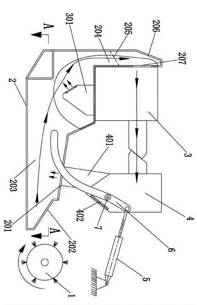
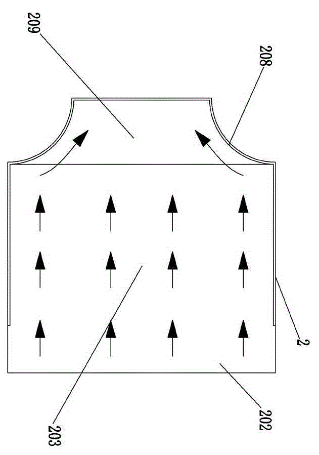
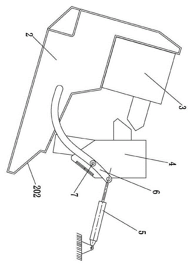
[0020] Such as Figure 1-4 As shown, a dust collection and dust removal system includes a sweeping brush 1, a dust collection bucket 2 with a box structure, a coarse filter mechanism 3, and a fine filter mechanism 4. The air outlet side of the coarse filter mechanism 3 is connected to the air inlet side of the fine filter mechanism 4. Pass; the dust collecting bucket 2 is provided with a dust inlet 202, and the sweeping brush 1 is arranged on the vehicle frame and faces the dust inlet 202 when cleaning. The tuyere 207; the fine filter mechanism 4 is provided with a blower fan 402 that can cause the internal negative pressure of the fine filter mechanism 4, and the dust collecting chamber 203 and the collecting chamber 204 that are connected to each other are arranged in the dust collecting bucket 2 in sequence according to the air flow direction. The dust chamber part 203 is in a horizontal state during cleaning, the dust collection chamber part 203 is connected to the dust in...


PUM


Abstract

The invention discloses a dust sucking and removing system in the technical field of environmental sanitary equipment. The dust sucking and removing system comprises a sweeping brush, a dust collecting hopper, a coarse filtering mechanism and a fine filtering mechanism; a draught fan which can cause the internal negative pressure of the fine filtering mechanism is arranged in the fine filtering mechanism, the coarse filtering mechanism is fixedly installed on the dust collecting hopper and provided with a dust falling barrel, and the dust falling barrel is communicated with a dust collecting cavity; the fine filtering mechanism is provided with a dust discharge barrel; when sweeping is performed, the air outlet side of the coarse filtering mechanism is close to the air inlet side of the fine filtering mechanism, and an outlet of the dust discharge barrel is close to a dust discharge port. The system further comprises a turnover mechanism which comprises a lever, a rotating shaft and a turnover oil cylinder, the lever is rotatably installed on a frame through the rotating shaft, one end of the lever is fixedly connected with the dust collecting hopper, the other end of the lever is hinged to a piston rod of the turnover oil cylinder, and a cylinder barrel of the turnover oil cylinder is hinged to the frame; when the system is in a dust pouring state, the air outlet side of the coarse filtering mechanism is separated from the air inlet side of the fine filtering mechanism, the outlet of the dust discharge barrel is separated from the dust discharge port, and therefore dust or sundries generated in the cleaning process can be conveniently poured.

Description

technical field [0001] The invention relates to the technical field of sanitation equipment, in particular to a dust suction and dust removal system for a mobile cleaning device. Background technique [0002] At present, mobile cleaning devices (such as sweeping vehicles and hand-held cleaning machines) are widely used, and they are collectively referred to as sanitation vehicles, which are mainly used in municipal engineering. At present, the dust removal system on sanitation vehicles is very complex. According to the dust collection process, it includes interconnected dust collection hoppers, coarse filter mechanisms, fine filter mechanisms, fans, and sweeping brushes facing the dust inlets of the dust collection hoppers. The built-in fans In the fine filter mechanism, when working, the fan operation creates negative pressure and forms an airflow to make the dust pass through the dust collecting hopper, the coarse filter mechanism, and the fine filter mechanism in turn. A ...

Claims


Application Information

Patent Timeline
IPC IPC(8): E01H1/08
CPCE01H1/0854E01H2001/0881
Inventor 陈彪
Owner YANGZHOU JINWEI ENVIRONMENTAL PROTECTION TECH CO LTD
Why Eureka
Try Eureka