ventilation system

A technology of ventilation system and channel, applied in the field of ventilation system, can solve the problems of shell damage and reduction of mechanical performance, etc.

Inactive Publication Date: 2019-06-04
WL GORE & ASSOC INC
View PDF8 Cites 0 Cited by
  • Summary
  • Abstract
  • Description
  • Claims
  • Application Information

AI Technical Summary

Problems solved by technology

Failure to drain water or other contaminants from each vehicle body can result in damage to the interior of the body, damage to components within the body, or other undesirable results, such as reduced mechanical properties

Method used


Image

  • ventilation system
  • ventilation system
  • ventilation system

Examples


example

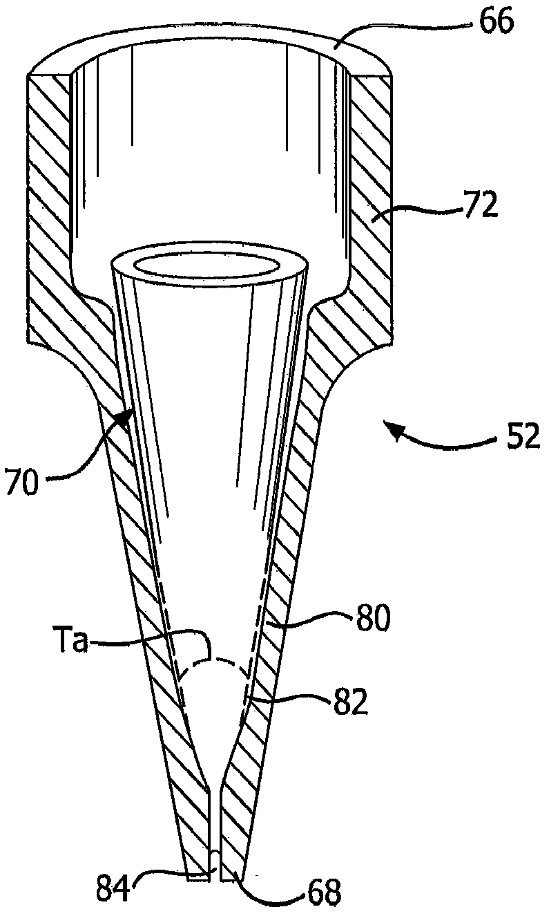
[0051] A valve constructed similar to valve 52 was constructed using stereolithography by injecting a viscoelastic elastomer into a molding tool followed by vulcanization to form a cross-linked elastomeric sample. The valve is made of RTV elastomer, silicone, with a hardness of about 60 Shore A. The slot geometry includes a slot thickness T of about 0.25 mm, a slot width W of about 5 mm minus the end chamfers or a maximum slot width W of about 2.25 mm including the end chamfers. During testing, the air flow of the valve of this example was measured to allow the required air flow, indicating that the valve had sufficient air flow to function as an effective vent for pressure equalization. During a liquid resistance test indicating the effectiveness of the flow control as a barrier to liquid flow, no passage of liquid lubricant was observed.


PUM

PropertyMeasurementUnit
Hardnessaaaaaaaaaa

Abstract

A ventilation system (10) for an enclosure (16) containing a liquid, the system comprising a ventilation module (12) including a housing defining a channel (30) and a flow control module (14) (24), a diaphragm (20) retained within the channel, and a sorbent (22) retained within the channel; the flow control module (14) is associated with the ventilation module and includes a valve (52) having an internal channel (70) , air can flow through the valve through the internal channel (70) in a first direction and a second opposite direction, wherein the flow control module (14) acts as a liquid to flow from the enclosure (16) towards the sorbent (22) through the valve (52) barrier pieces.

Description

technical field [0001] In general, the present invention relates to various embodiments of systems, methods, and apparatus for ventilating enclosures. Certain embodiments relate more particularly to venting enclosures containing synthetic or non-synthetic oil-based products, such as enclosures containing machinery and lubricants. Background technique [0002] Gas-permeable, liquid-impermeable ventilation finds use in a variety of applications in the automotive industry, such as electrical component housings, gear housings, bodywork and brakes, for example where a pressure balance between the interior of the housing and the surrounding environment is required case. Mechanical enclosures, such as gearbox housings and shafts, are often subjected to thermal cycling. When the machine is running, the temperature of the lubricant and the air inside starts to rise, which increases the pressure of the air inside the enclosure. When the machinery shuts down, the temperature and pre...

Claims


Application Information

Patent Timeline
IPC IPC(8): F16H57/027F16K15/14F16K17/34F16K24/00F15B21/044
CPCF15B21/044F16K15/147F16K17/34F16K24/00
Inventor D·E·巴山姆N·隆巴迪
Owner WL GORE & ASSOC INC
Why Eureka
Try Eureka