Low-speed state stably-accelerating throttle valve

A throttle and throttle shaft technology, applied in engine control, machine/engine, mechanical equipment, etc., can solve the problems of precise control of flow balance between two throttle valves and difficult adjustment methods, so as to avoid sudden and sudden increase , stable change, precise control effect

Inactive Publication Date: 2016-03-16
CHONGQING YUHUI MACHINERY
View PDF5 Cites 0 Cited by
  • Summary
  • Abstract
  • Description
  • Claims
  • Application Information

AI Technical Summary

Problems solved by technology

The traditional mechanical throttle valve is generally a single-cylinder throttle valve; the adjustment of the intake air volume is often controlled by adjusting the angle of the throttle plate to control the intake air volume; this adjustment method is relatively difficult, especially for flow balance. adjustment, it is not easy to achieve precise control of the flow balance of the two throttle valves in non-idling state

Method used


Image

  • Low-speed state stably-accelerating throttle valve
  • Low-speed state stably-accelerating throttle valve
  • Low-speed state stably-accelerating throttle valve

Examples


Embodiment 1

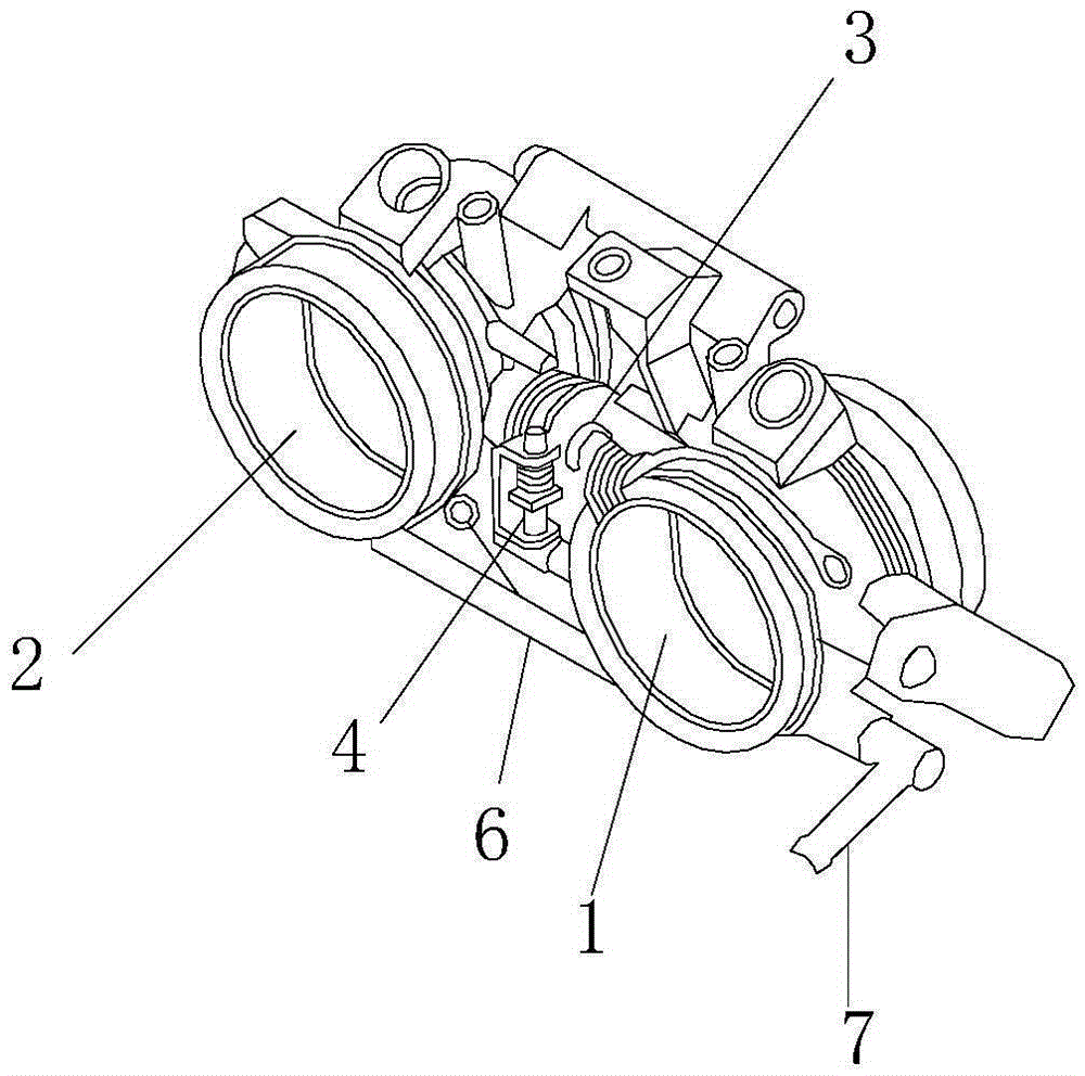
[0055] As shown in the figure, a throttle valve for a two-cylinder engine provided in this embodiment includes a first throttle valve 1, a second throttle valve 2 and a connecting mechanism 3;

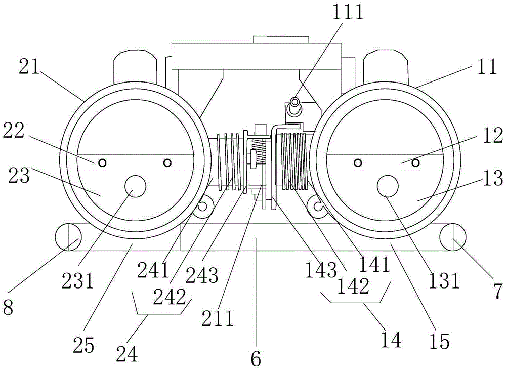
[0056] The first throttle valve includes a first throttle body 11, a first throttle shaft 12, a first throttle plate 13 and a first return mechanism 14; the first throttle shaft extends along the radial direction of the first throttle body Setting; the first throttle plate is set along the first throttle shaft; the first throttle plate is used to control the air flow of the pipeline formed by the first throttle body; the first return mechanism is set on the first The throttle body is connected to the first throttle shaft; the first return mechanism is used to restore the idle state of the first throttle plate;

[0057]The second throttle valve includes a second throttle body 21, a second throttle shaft 22, a second throttle plate 23 and a first return mechanism 24; the second throttle ...

Embodiment 2

[0096] The dual-cylinder engine throttle valve provided by this embodiment, the throttle valve body provided by this embodiment is made of aluminum die-casting, and then the throttle valves of two kinds of master-slave mechanisms that produce throttle valves are set on the main body; two throttle valves The diameters are 46 to 52mm respectively, and are used for two engine displacements; the first throttle valve provided in this embodiment is arranged on the right side of the main body, and the throttle valve is the master cylinder valve; the second throttle valve is arranged on the left side, and the throttle valve is Auxiliary cylinder throttle; there is a mud-proof cover between the main and auxiliary cylinder throttle; the mud-proof cover must be between the two throttles; the fuel injector and fuel rail are assembled on the engine assembly line; the fuel injector is installed on the on the subject. The fuel injector and fuel rail are fixed on the main body, and the fuel r...


PUM

PropertyMeasurementUnit
Diameteraaaaaaaaaa
Diameteraaaaaaaaaa

Abstract

The invention discloses a low-speed state stably-accelerating throttle valve which comprises a first throttle valve body, a second throttle valve body and a connecting mechanism. A first return mechanism of the first throttle valve and a second return mechanism of the second throttle valve body are connected through the connecting mechanism to form a double-cylinder throttle valve body. The connecting mechanism is used for controlling the rotating angle of throttle valve pieces of the first throttle valve body and the second throttle valve body, and spherical arc faces are arranged on the inner side walls of the first throttle valve body and the second throttle valve body. According to the low-speed state stably-accelerating throttle valve, the spherical arc faces are arranged on the inner side faces of the double-cylinder throttle valve body so that the change of the air inlet flow of the throttle valve pieces can be more stable when the opening angle is small, the phenomenon that the air inlet flow is suddenly increased is avoided, and accurate control over the flow in the small opening angle state is achieved. Meanwhile, under the control of a synchronous adjusting mechanism, the throttle valve is adjusted, and accurate control is achieved in the state of the balanced inflow of the main and auxiliary throttle valve bodies.

Description

technical field [0001] The invention relates to the field of engine air intake system components, in particular to a throttle valve for smooth acceleration in a low-speed state. Background technique [0002] The mechanical throttle body of the intake system of the internal combustion engine is mainly composed of a throttle shaft installed in the throttle through a bearing, and a throttle plate installed on the throttle shaft and arranged in the main air flow passage. The throttle plate is connected with the accelerator pedal lever in the cab through the steel wire rope installed and fixed on the swing frame assembly and the bracket. The driver steps on the accelerator pedal and transmits the force to the swing frame assembly to rotate the throttle shaft to control the opening of the throttle plate. Angle, so as to change the area of ​​the air intake passage of the middle throttle, so as to adjust the air intake into the engine, and meet the air flow requirements of the engin...

Claims


Application Information

Patent Timeline
IPC IPC(8): F02D9/08F02D9/10
Inventor 李维张建和杨大明
Owner CHONGQING YUHUI MACHINERY
Why Eureka
Try Eureka