
Oil well cavitation method physicochemical heat blockage relieving technology

A legal and oil well technology, applied in the field of physical and chemical thermal blockage removal technology of oil well cavitation method, can solve the problems of low temperature of injection liquid, inconvenient popularization and application, affecting chemical reaction, etc. simple effect

Inactive Publication Date: 2016-03-16
克拉玛依新科澳石油天然气技术股份有限公司
View PDF7 Cites 4 Cited by
  • Summary
  • Abstract
  • Description
  • Claims
  • Application Information

AI Technical Summary

Problems solved by technology

The disadvantages of this method are: field operation, low temperature of the injection fluid (especially in winter), large displacement and rapid injection, resulting in a decrease in the temperature of the formation for a period of time and affecting the chemical reaction
[0012] The disadvantages of physical blocking technology are: complex equipment, high cost or difficult operation and inconvenient popularization and application

Method used


Image

  • Oil well cavitation method physicochemical heat blockage relieving technology
  • Oil well cavitation method physicochemical heat blockage relieving technology
  • Oil well cavitation method physicochemical heat blockage relieving technology

Examples


Embodiment 1

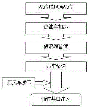
[0042] Embodiment 1: as attached figure 2 As shown, the working system is composed of a liquid distribution tank, a hot oil truck, a pump truck, a wind press, and ground pipeline connections; the liquid is prepared in the liquid distribution tank or at the liquid distribution station, heated by a hot oil truck, connected to the liquid storage tank, and then The injection is injected through the wellhead under pressure by the pump truck with the assistance of the wind press.

[0043] The construction process is:

[0044] 1. Preparations before construction: Check that the wellhead and wellbore meet the construction conditions; connect ground equipment and pipelines; detect high-pressure manifolds and various components, and conduct pressure tests on pipelines to ensure that the pipelines are pressure-bearing.

[0045] 2. Preparation of blockage-removing liquid: prepare blockage-removing liquid in the liquid dispensing tank according to the design formula and liquid volume, or...

Embodiment 2

[0048] Embodiment 2: as attached image 3 As shown, there is no major change in the process system, and different liquid preparation methods and heating methods can be used. In the present invention, the core of the heating device principle is energy conversion, and the most extensive one is the conversion of electrical energy into thermal energy. When conditions permit, electric energy and other methods can also be used for heating.

[0049] In the above, the working system uses surface pump trucks to establish a controllable and periodic oil layer plugging removal process system for oil layers, which can work together with different types of plugging fluids. Send it downhole to make it generate high-speed liquid flow in the wellbore.

[0050] In the foregoing, construction equipment should be versatile for the same type of operation. To adapt to the nature of the fluid medium; to be able to cope with the adjustment of injection parameters. Commonly used construction equi...


PUM


Abstract

The invention discloses an oil well cavitation method physicochemical heat blockage relieving technology. A fluid container or a fluid loading tank truck, a heating pump truck, a fluid storage tank, an injection pump truck and a wind pressing truck are sequentially connected through a pipeline. A system is implemented in the manner that blockage relieving fluid is heated and pumped into an inlet device to be injected through a well mouth; the heating temperature is set to be the design temperature and is higher than the temperature of a scaling and paraffinning point; the blockage relieving fluid is heated through the heating pump truck, the chemical reaction speed of the blockage relieving fluid is increased, and physical heat washing is carried out on a blockage; and at the final period of the pumping process, gas is mixed in the blockage relieving fluid through the wind pressing truck, meanwhile, the blockage relieving fluid is heated, the gas heating, expanding, overflowing and debacle process happens in a shaft and a stratum, and the chemical blockage relieving is assisted through cavitation. The physical blockage relieving technology and the chemical blockage relieving technology are organically combined, and the overall blockage relieving effect is improved. The design is novel, the technology is simple, construction is convenient, one-time investment is low, viscosity reduction, paraffin removing and preventing and blockage relieving are carried out on an oil well, and the oil well chemical method blockage relieving effect is improved.

Description

technical field [0001] The invention relates to a method or equipment and device technology for oil gas drilling repair and flushing of boreholes under IPC international patent classification E21B, in particular to a physical, chemical, thermal plugging removal process of oil well cavitation method. Background technique [0002] In the process of oil field development, due to the hydration expansion of clay in the oil reservoir, particle migration, scaling, wax precipitation, suspended solids in the injection water, bacteria, oil pollution, incompatibility of the well fluid, etc., the oil well and the vicinity of the water well will be blocked. The clogging types that form oil wells include two-phase flow clogging, colloidal, waxy, asphaltene clogging, emulsified clogging, fracture closure clogging and fracture throat grit settlement clogging, etc., leading to production decline. The direct consequence of damage to the formation is that the permeability of the oil layer decr...

Claims


Application Information

Patent Timeline
IPC IPC(8): E21B36/00E21B37/06
CPCE21B36/00E21B37/06
Inventor 赵虹蔚立军龚朝国
Owner 克拉玛依新科澳石油天然气技术股份有限公司
Learn More