
Soymilk machine with separate motor and blade

A soymilk machine and blade technology, applied in beverage preparation devices, household appliances, applications, etc., can solve problems such as machine head damage, motor temperature rise, difficult cleaning, etc., to prevent water ingress, increase service life, and facilitate cleaning. Effect

Active Publication Date: 2018-08-10
HANGZHOU SINODOD ELECTRIC
View PDF6 Cites 0 Cited by
  • Summary
  • Abstract
  • Description
  • Claims
  • Application Information

AI Technical Summary

Problems solved by technology

[0002] The existing soymilk machine is composed of two parts: the machine head and the cup body. The machine head is placed inside the cup body to realize the preheating, beating and cooking functions of the soymilk machine. There is a motor inside the machine head, and a blade is designed at the end of the motor shaft. Drive the blade to rotate to realize the bean beating function of the soymilk machine, and the bottom of the cup body is designed with a heating tube to heat the soymilk machine to realize the cooking function of the soymilk machine; the motor and circuit board are designed in the head of the existing soymilk machine, and heat dissipation is required inside the head. The machine head cannot be sealed, and the machine head is easily damaged by water ingress during cleaning, and the blade and net cover are designed at the end of the machine head, making it difficult to clean the machine head. The structure of the machine head is complex and the machine head is heavy
Existing soymilk machines consist of a machine head and a cup body, the machine head and the cup body are connected by a coupler, the motor is designed inside the machine head, and the blade is fixed at the end of the motor shaft, resulting in a complex structure of the machine head that is difficult to clean and difficult to realize. Waterproof; and the motor is placed in a heated high-temperature environment, causing the temperature rise of the motor to be too high, making it difficult to work for a long time

Method used


Image

  • Soymilk machine with separate motor and blade
  • Soymilk machine with separate motor and blade
  • Soymilk machine with separate motor and blade

Examples


Embodiment Construction

[0019] Below in conjunction with accompanying drawing, the present invention will be further described:

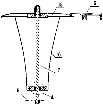
[0020] A soymilk machine in which the motor and the blade are separated, including a machine base 1, a cup body 2, a machine head and a blade 5, a motor 4 is arranged in the machine head, and a motor mounting seat 3 is extended upward on one side of the machine base, and the motor 4 can be installed on the motor The seat moves up and down; the cup body 2 is arranged on the machine base, a cup cover 6 is arranged on the cup body 2, a connecting shaft 7 is arranged in the center of the cup cover 6, the blade 5 is arranged at the lower end of the connecting shaft 7, and the upper end of the connecting shaft 7 is connected to the motor The output shaft of the motor drives the rotation of the connecting shaft through the rotation of the motor, and finally drives the blade to rotate to crush the beans. The invention separates the design of the motor from the blade, and the motor...


PUM


Abstract

The invention relates to a soybean milk machine with a motor and a blade separated from each other. The soybean milk machine is characterized by comprising a machine base, a cup body, a machine head and the blade; the motor is arranged in the machine head, one side of the machine base extends upwards to form a motor installation seat, and the motor can move up and down in the motor installation seat; the cup body is arranged in the machine base, the cup body is provided with a cup lid, a connecting shaft is arranged in the center of the cup lid, the blade is arranged at the lower end of the connecting shaft, and the upper end of the connecting shaft is connected with an output shaft of the motor. According to the soybean milk machine, the motor is separated from the blade, the motor can stretch freely in the motor installation seat, the motor part extends downwards to be attached to the upper end face of the cup lid only by pressing the top of the motor protruding out of the opening end of the motor installation seat, and connection between the output shaft of the motor and the connecting shaft is achieved; after soybean milk is made, the motor can return to the original position under the action of a spring by poking the upper end of a motor limiting buckle, and separation between the motor and the blade is achieved; when cleaning is conducted, the motor part is not cleaned, and water is prevented from entering the motor.

Description

technical field [0001] The invention relates to a soybean milk machine in which a motor and a blade are separated. Background technique [0002] The existing soymilk machine is composed of two parts: the machine head and the cup body. The machine head is placed inside the cup body to realize the preheating, beating and cooking functions of the soymilk machine. There is a motor inside the machine head, and a blade is designed at the end of the motor shaft. Drive the blade to rotate to realize the bean beating function of the soymilk machine, and the bottom of the cup body is designed with a heating tube to heat the soymilk machine to realize the cooking function of the soymilk machine; the motor and circuit board are designed in the head of the existing soymilk machine, and heat dissipation is required inside the head. The machine head cannot be sealed, and the machine head is easily damaged by water ingress during cleaning, and the blade and net cover are designed at the end...

Claims


Application Information

Patent Timeline
Patent Type & Authority Patents(China)
IPC IPC(8): A47J31/00A47J31/44
CPCA47J31/00A47J31/44
Inventor 高新忠孙亮邓杰
Owner HANGZHOU SINODOD ELECTRIC
Learn More