Compressor with pressure limiting

A compressor and pressure technology, which is applied in the field of compression, can solve the problems of air dead volume reduction efficiency, etc., and achieve the effect of improving efficiency

Active Publication Date: 2016-03-09
CONTINENTAL REIFEN DEUTSCHLAND GMBH
View PDF7 Cites 2 Cited by
  • Summary
  • Abstract
  • Description
  • Claims
  • Application Information

AI Technical Summary

Problems solved by technology

However, a correspondingly designed air dead volume in the compressor reduces its efficiency and requires such unnecessarily large or expensive compressors for achieving the predetermined specifications

Method used


Image

  • Compressor with pressure limiting
  • Compressor with pressure limiting
  • Compressor with pressure limiting

Examples


Embodiment Construction

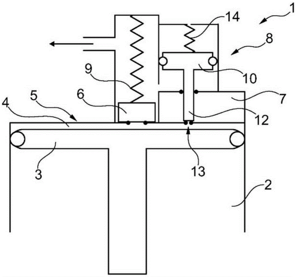
[0027] figure 1 with figure 2 An embodiment of a compression unit according to the invention in a portable source of compressed air not shown further here is shown schematically and largely schematically as a schematic diagram for sealing motor vehicle tires in the event of air loss and pump gas. figure 1 This normal state is shown. figure 2 The state is shown with the second air dead volume switched on.

[0028] The compression unit has a reciprocating-piston compressor 1 driven by a slide-and-crank drive, also not shown here, with a piston 3 that moves vibratingly in a cylinder 2 , which defines the A compression chamber is provided with a first air dead volume 4 , the cylinder being closed on the output side by a cylinder head 5 with an outlet valve 6 .

[0029] The reciprocating piston compressor 1 has a second air dead volume 7 which can be connected to the compression chamber via a valve 8 . The valve 8 can be opened depending on the pressure in the outlet duct 9 ...


PUM


Abstract

A compressor unit in a portable compressed air source, comprising a reciprocating piston compressor which is driven by a slider crank mechanism and has a piston which is moved in reciprocation in a cylinder, said piston delimiting a compression chamber which has a first dead air volume. The cylinder exit is closed off by a cylinder head with an exhaust valve, and the compression chamber can be connected by a valve to at least one other dead air volume.

Description

technical field [0001] The invention relates to a compressor unit in a portable source of compressed air, the compressor unit having a reciprocating piston compressor driven by a slider crank gear (Schubkurbelgetriebe), the reciprocating piston compressor having an internal cylinder A vibratingly moving piston delimits a compression chamber provided with a first air dead volume, wherein the cylinder is closed on the output side by a cylinder head with an outlet valve. Background technique [0002] Such compressor units are for example required with or as part of means for sealing and pumping inflatable objects, especially for sealing and pumping motor vehicle tires (repair kits). [0003] These portable and lightweight units contain a compressor unit as a source of compressed air, in addition, a sealant container for automatic sealant that can be filled into inflatable objects, a container for sealant and compressed air A valve unit and a dispensing unit, and are provided w...

Claims


Application Information

Patent Timeline
IPC IPC(8): F04B35/04F04B39/00F04B39/10F04B39/12F04B49/02F04B49/03F04B49/12F04B35/06F04B49/08F04B49/22
CPCB29C73/166F04B35/04F04B35/06F04B39/0016F04B39/10F04B39/125F04B49/02F04B49/022F04B49/03F04B49/08F04B49/12F04B49/225
Inventor 克里斯托夫·曹姆赖纳·德特林
Owner CONTINENTAL REIFEN DEUTSCHLAND GMBH
Why Eureka
Try Eureka