
Monitoring system for power supply status

A technology of power supply status and monitoring system, applied in the direction of non-electrical signal transmission system, signal transmission system, measuring electricity, etc., can solve the problem of low detection efficiency, achieve fast acquisition and solve the effect of low monitoring efficiency

Active Publication Date: 2019-06-21
STATE GRID BEIJING ELECTRIC POWER +1
View PDF6 Cites 0 Cited by
  • Summary
  • Abstract
  • Description
  • Claims
  • Application Information

AI Technical Summary

Problems solved by technology

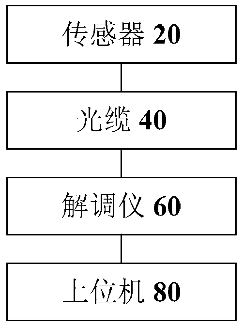
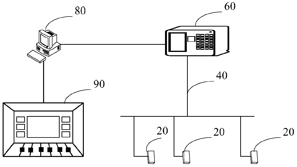
[0004] An embodiment of the present invention provides a power supply state monitoring system to at least solve the technical problem of low detection efficiency of the existing power supply state monitoring system

Method used


Image

  • Monitoring system for power supply status
  • Monitoring system for power supply status
  • Monitoring system for power supply status

Examples


Embodiment Construction

[0019] In order to enable those skilled in the art to better understand the solutions of the present invention, the following will clearly and completely describe the technical solutions in the embodiments of the present invention in conjunction with the drawings in the embodiments of the present invention. Obviously, the described embodiments are only It is an embodiment of a part of the present invention, but not all embodiments. Based on the embodiments of the present invention, all other embodiments obtained by persons of ordinary skill in the art without making creative efforts shall fall within the protection scope of the present invention.

[0020] It should be noted that the terms "first" and "second" in the description and claims of the present invention and the above drawings are used to distinguish similar objects, but not necessarily used to describe a specific sequence or sequence. It is to be understood that the data so used are interchangeable under appropriate ...


PUM


Abstract

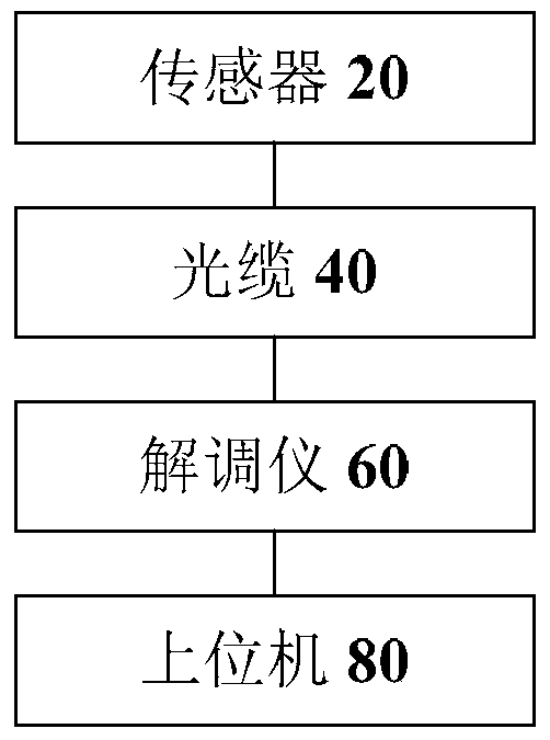
The invention discloses a power supply state monitoring system. The monitoring system comprises a sensor used for detecting the power supply state signals of an electricity utilization client end in real time and generating optical signals recording the power supply state signals, an optical cable which is connected with the sensor and is use for transmitting the optical signals recording the power supply state signals, a demodulation instrument which is connected with the optical cable and is used for demodulating the optical signals into electric signals, and a PC which is used for determining the power supply state of the electricity utilization client end as a normal state or a power outage state based on the electric signals. With the power supply state monitoring system of the invention adopted, the technical problems of low monitoring efficiency of an existing power supply state monitoring system can be solved.

Description

technical field [0001] The invention relates to the field of power system monitoring, in particular to a monitoring system for power supply status. Background technique [0002] The deepening of power system reform and changes in market supply and demand have transformed power supply companies from managers of power supply and use into power operators and service providers. Especially in recent years, the variety and quantity of household appliances for residents have been increasing, and electricity has become a basic element of residents' daily life. Residents are more and more dependent on electricity consumption, and their requirements for power quality and reliability of power supply are also getting higher and higher. However, in the existing power monitoring system, manual monitoring has a slow fault feedback speed, and the power grid maintenance takes a long time, seriously affecting people's normal electricity consumption. [0003] Aiming at the above-mentioned te...

Claims


Application Information

Patent Timeline
Patent Type & Authority Patents(China)
IPC IPC(8): G01R31/00G08C23/06
CPCG01R31/002G08C23/06
Inventor 李捷张坤明邢钊
Owner STATE GRID BEIJING ELECTRIC POWER
Learn More