A splicing die

A spliced, concave die technology, applied in the field of mechanical forging, can solve the problems of die wear and tear, and achieve the effect of improving the life of the die, improving the work efficiency, and improving the life of the die.

Active Publication Date: 2017-11-17
浙江铭锐金属制品股份有限公司
View PDF6 Cites 0 Cited by
  • Summary
  • Abstract
  • Description
  • Claims
  • Application Information

AI Technical Summary

Problems solved by technology

[0003] The purpose of the present invention is to overcome the problem of early wear and tear of the mold due to the local stress of the mold, and to provide a lower mold that disperses the stress concentrated on the lower mold step by step to protect the mold. effect

Method used


Image

  • A splicing die
  • A splicing die
  • A splicing die

Examples


Embodiment 1

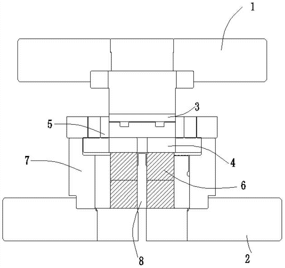
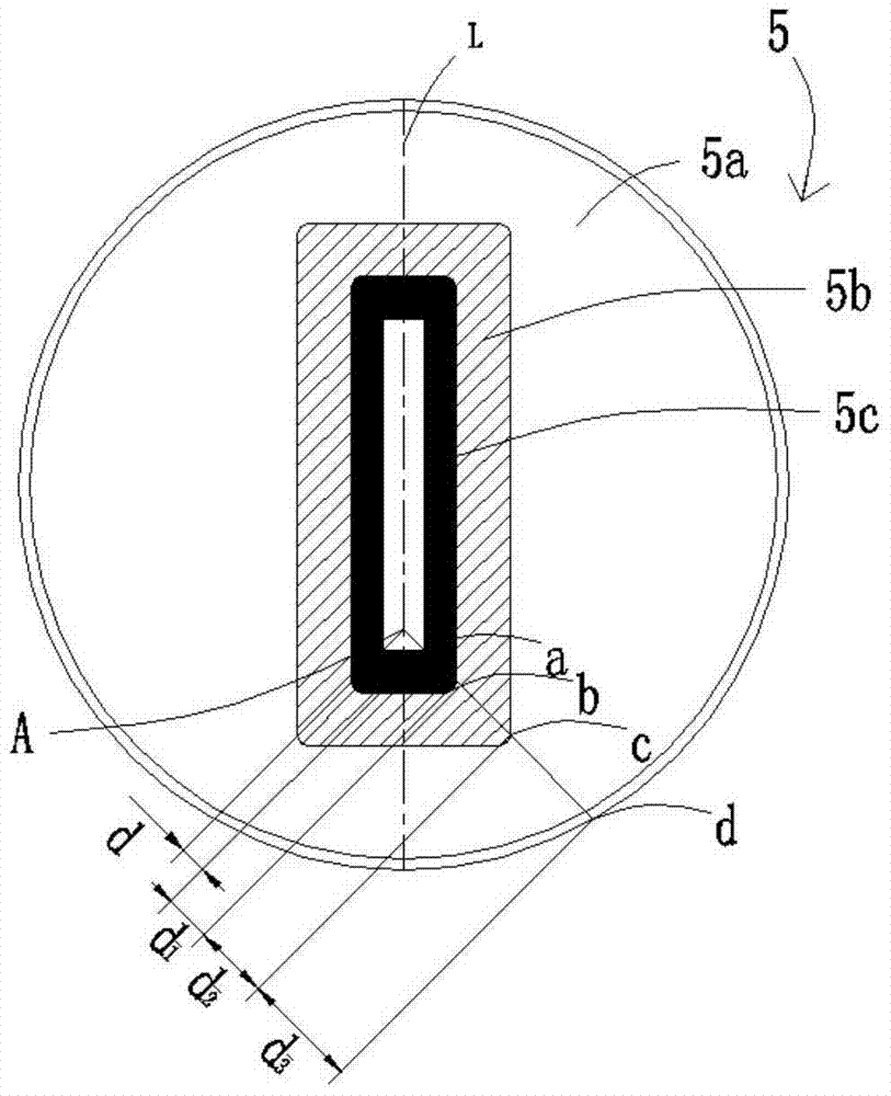
[0028] Picture 1-1 A schematic diagram of an extrusion machine for an automobile exhaust pipe pressure device applying a splicing die of the present invention, Figure 1-2 It is a schematic diagram of Embodiment 1 of a spliced ​​die of the present invention, figure 2 It is a schematic diagram of the outer insert 5a of the lower mold in Embodiment 1, image 3 It is a schematic diagram of the inner insert 5b of the lower mold in Embodiment 1, Figure 4 It is a schematic diagram of the central insert 5c of the lower mold in the first embodiment. Such as Picture 1-1 , Figure 1-2 , figure 2 , image 3 and Figure 4 As shown, this embodiment 1 provides a stamping machine for an automobile exhaust pipe pressure device, including an upper mold base 1, a lower mold base 2, an upper mold 3, an extrusion base plate 4, a lower mold 5, and a load-bearing platform 6 , fixed plate 7 and thimble bar 8. The upper mold base 1 is fixedly connected with the upper mold 3, the extrusion...


PUM

PropertyMeasurementUnit
hardnessaaaaaaaaaa
hardnessaaaaaaaaaa
hardnessaaaaaaaaaa

Abstract

The invention relates to a spliced ​​concave mold, which comprises an outer insert, an inner insert and a center insert; the center insert is fixedly arranged in the inner insert; the inner insert is fixedly arranged in the outer insert; the cross section of the outer insert is Circular, with a rectangular hollow in the center; the inner insert is rectangular in cross-section, with a rectangular hollow in the center; the central insert matches the size of the second rectangular hollow, with a rectangular cross-section, and a rectangular hollow in the center; the outer The insert is made of SKD61, the inner insert is made of SKD61, and the center insert is made of SKH51; the outer insert, the inner insert and the center insert are fitted in an interference fit. The invention solves the problems of easy cracking and short service life of the lower die, improves the service life of the lower die and increases working efficiency.

Description

technical field [0001] The invention relates to the field of mechanical forging, in particular to a spliced ​​die. Background technique [0002] As a kind of forging equipment, the extruder is often widely used in the casting process. It relies on the extruder to exert external force on the material to cause plastic deformation of the material, so as to obtain the extruded parts of the required shape and size. In the extrusion process, the stress of the cold extrusion punch varies with the extrusion method. The forward extrusion punch is mainly subjected to the compressive stress, while the reverse extrusion punch or the composite extrusion punch is under the extrusion process. During the working stroke, it is subjected to a large compressive stress, and it is subjected to a small tensile stress during the return journey. The tensile and compressive stresses are generated alternately. Whether it is forward extrusion or reverse extrusion, it is often affected by bending stre...

Claims


Application Information

Patent Timeline
Patent Type & Authority Patents(China)
IPC IPC(8): B21C25/02
Inventor 许峰
Owner 浙江铭锐金属制品股份有限公司
Why Eureka
Try Eureka