
A Diaphragm Pump Diaphragm Fatigue Testing Machine

A technology of fatigue testing machine and diaphragm pump, which is applied in the field of fatigue testing machine, can solve the problems of long time consumption and high power consumption, and achieve the effects of reducing power usage, improving efficiency and reducing friction

Active Publication Date: 2018-06-26
MILTON ROY IND SHANGHAI
View PDF6 Cites 0 Cited by
  • Summary
  • Abstract
  • Description
  • Claims
  • Application Information

AI Technical Summary

Problems solved by technology

[0003] Diaphragm pump is a kind of non-leakage pump. It depends on the back and forth agitation of a diaphragm to change the volume of the working chamber to inhale and discharge liquid. The working frequency of the diaphragm is generally 30-200 times per minute. The conventional test method costs a lot of money. For a long time, and the stress test requires a lot of power consumption

Method used


Image

  • A Diaphragm Pump Diaphragm Fatigue Testing Machine
  • A Diaphragm Pump Diaphragm Fatigue Testing Machine

Examples


Embodiment Construction

[0020] The present invention will be described in detail below in conjunction with the accompanying drawings and specific embodiments.

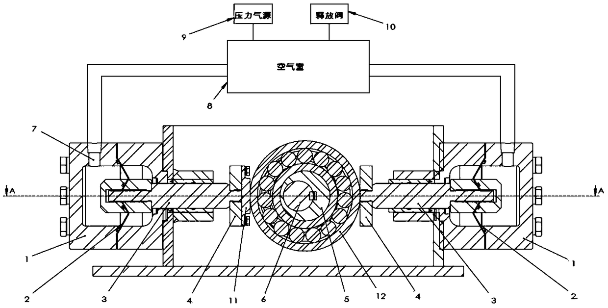
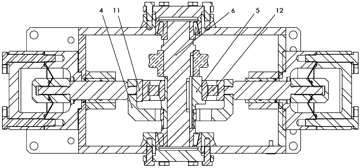
[0021] like figure 1 As shown in -2, a diaphragm fatigue testing machine for a diaphragm pump includes a drive unit, a linkage unit, a pump head 1 and a pressure control unit connected in sequence.

[0022] The drive unit includes an eccentric wheel 5 and a drive shaft 6. The drive shaft 6 is sleeved in the eccentric wheel 5. The outer edge of the eccentric wheel 5 is covered with a rolling bearing 12 to reduce friction loss. The drive shaft 6 The eccentric wheel 5 is driven to rotate under the drive of the motor.

[0023] The linkage unit includes a U-shaped drive block 4 and a plunger rod 3. The U-shaped drive block 4 is connected to a rolling bearing 12, and a wear-resistant backing plate 11 is provided at the joint to reduce the friction between the U-shaped drive block and the rolling bearing. , to extend the service life, one end of t...


PUM


Abstract

The invention relates to a fatigue testing machine for diaphragms of a diaphragm pump. The fatigue testing machine comprises a drive unit, linkage units, pump heads (1) and a pressure control unit which are sequentially connected, wherein two groups of the linkage units and the pump heads (1) are provided, and are symmetrical about the left-and-right centre of the drive unit respectively; and during fatigue testing, one diaphragm (2) is placed in each pump head (1), and connected to the corresponding linkage unit, the pressure control unit applies pressure on the diaphragms (2), and the drive unit drives the linkage units to carry out left-and-right reciprocating motions under the driving of a motor, and then drives the diaphragms (2) to vibrate. Compared with the prior art, the fatigue testing machine disclosed by the invention has the advantages of being low in power consumption, high in frequency, and the like.

Description

technical field [0001] The invention relates to a fatigue testing machine, in particular to a diaphragm pump diaphragm fatigue testing machine. Background technique [0002] Diaphragm pump, also known as control pump, is the main type of actuator. By receiving the control signal output by the adjustment control unit, it uses power operation to change the fluid flow. The role of the diaphragm pump in process control is to accept the control signal of the regulator or computer, change the flow rate of the regulated medium, and maintain the regulated parameters within the required range, so as to achieve the automation of the production process. Diaphragm pumps are included in the automatic selection of quick and easy optimization. If the automatic adjustment system is compared with the manual adjustment process, the detection unit is the human eye, and the adjustment control unit is the human brain, then the execution unit—diaphragm pump is the human hands and feet. . Diaphr...

Claims


Application Information

Patent Timeline
Patent Type & Authority Patents(China)
IPC IPC(8): F04B51/00
CPCF04B51/00
Inventor 付家全卫中山陈建国
Owner MILTON ROY IND SHANGHAI
Learn More