
Novel heat accumulating type compressed air energy storage system

A technology of compressed air energy storage and compressed air, applied in gas turbine installations, machines/engines, mechanical equipment, etc., can solve the problems of low system operation efficiency, low heat energy utilization rate, unreasonable system flow, etc., and achieve simple and compact structure, High system efficiency and good heat exchange effect

Active Publication Date: 2016-03-02
INST OF ENGINEERING THERMOPHYSICS - CHINESE ACAD OF SCI
View PDF6 Cites 26 Cited by
  • Summary
  • Abstract
  • Description
  • Claims
  • Application Information

AI Technical Summary

Problems solved by technology

However, the current regenerative compressed air energy storage system has problems such as repeated arrangement of inter-stage heat exchangers, unreasonable system flow, large area occupation, high cost, low thermal energy utilization rate and the resulting reduction in system operating efficiency.

Method used


Image

  • Novel heat accumulating type compressed air energy storage system
  • Novel heat accumulating type compressed air energy storage system

Examples


Embodiment 1

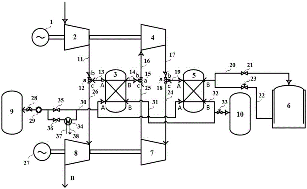
[0032] Such as figure 1 As shown, the novel regenerative compressed air energy storage system of the present invention includes: drive unit 1, compressors 2 and 4, heat exchangers 3 and 5, compressed air storage device 6, expanders 7 and 8, generator 27. Cold tank 9, hot tank 10, three-way reversing valve 12, 15 and 18, pump 29, valves 21, 23, 28 and 33, pipelines 11, 13, 14, 16, 17, 19, 20, 22, 24, 25, 26, 30, 31 and 32.

[0033] Specifically, the novel regenerative compressed air energy storage system of the present invention includes compressor units 2, 4, heat storage system, expansion units 7, 8 and compressed air storage device 6, and the compressor units 2, 4 include at least two-stage compressors, Wherein, the inlet of the first-stage compressor 2 is connected to the air source A, and the last-stage heat exchanger 5 is arranged on the ventilation pipeline between the outlet of the last-stage compressor 4 and the inlet of the compressed air storage device 6, with two a...

Embodiment 2

[0045] Such as figure 2 As shown, the main structure of Embodiment 2 of the present invention is the same as that of Embodiment 1, and a cooler 34, valves 35 and 36, and pipelines 37 and 38 connected to the outside world are added. Wherein, during energy storage, valve 36 is closed and valve 35 is opened, and the working process is consistent with Embodiment 1; when energy is released, valve 35 is closed and valve 36 is opened. The temperature of the heat exchange medium coming out of the liquid side enables the cold tank 9 to provide a lower temperature heat exchange medium for the liquid sides of the heat exchangers 3 and 5 during the energy storage stage, further enhancing the heat storage capacity and improving the system efficiency. In addition, the pipelines 37 and 38 connecting the cooler 34 with the outside world can be connected with systems such as heat pumps, so that they can be used for different purposes such as air conditioning and refrigeration.


PUM


Abstract

The invention discloses a novel heat accumulating type compressed air energy storage system. On the basis of a heat accumulating type compressed air energy storage system, work procedures of the system are optimized, by the characteristic that a compressor unit and an expansion unit share a heat exchanger, the compressor unit, a heat accumulating system and the expansion unit are coupled together well through a three-way reversing valve, and problems that interstage heat exchangers of the heat accumulating type compressed air energy storage system are arranged repeatedly, system processes are not reasonable, excessive lands are occupied, cost is high, heat energy utilization rate is low, then system running efficiency is reduced and the like are solved. The novel heat accumulating type compressed air energy storage system has the advantages of simple and compact structure, high system efficiency, good heat exchange effect, low manufacturing cost and the like.

Description

technical field [0001] The invention relates to the technical field of energy storage, in particular to a novel regenerative compressed air energy storage system. Background technique [0002] The traditional compressed air energy storage system is an energy storage system developed based on gas turbine technology. The working principle is: during low power consumption, the air is compressed and stored in the gas storage chamber, so that the internal energy converted from electric energy into air is stored; during the peak power consumption, high-pressure air is released from the gas storage chamber and enters the combustion chamber of the gas turbine together with the fuel. Combustion, and then drive the turbine to generate electricity. One of the problems of traditional compressed air energy storage systems is that they still rely on burning fossil fuels to provide heat sources. On the one hand, they are facing the threat of fossil fuels being depleted and prices rising. ...

Claims


Application Information

Patent Timeline
Patent Type & Authority Applications(China)
IPC IPC(8): F02C6/16
CPCF02C6/16Y02E60/16
Inventor 周学志徐玉杰王亮刘畅陈海生
Owner INST OF ENGINEERING THERMOPHYSICS - CHINESE ACAD OF SCI
Learn More