Eureka AIR delivers breakthrough ideas for toughest innovation challenges, trusted by R&D personnel around the world.

Mixing matrix estimation method aiming at underdetermined blind source separation

An underdetermined blind source separation and mixing matrix technology is applied in the field of mixing matrix estimation for underdetermined blind source separation. The effect of precision

Active Publication Date: 2016-02-24
HARBIN ENG UNIV
View PDF5 Cites 13 Cited by
  • Summary
  • Abstract
  • Description
  • Claims
  • Application Information

AI Technical Summary

Problems solved by technology

This method has low complexity and is easy to implement, but its performance is easily affected by the initial value, and the number of source signals needs to be given, but the actual number of source signals may be unknown
Zhang Ye proposed a potential function method in the article "Estimation of Source Number in Underdetermined Blind Separation Based on Laplace Potential Function" published in Signal Processing Journal Vol. 25, No. 11. When the mixing matrix is ​​estimated, but this method lacks a certain theoretical basis, the subjective experience is too strong, and it is only applicable to two-dimensional space
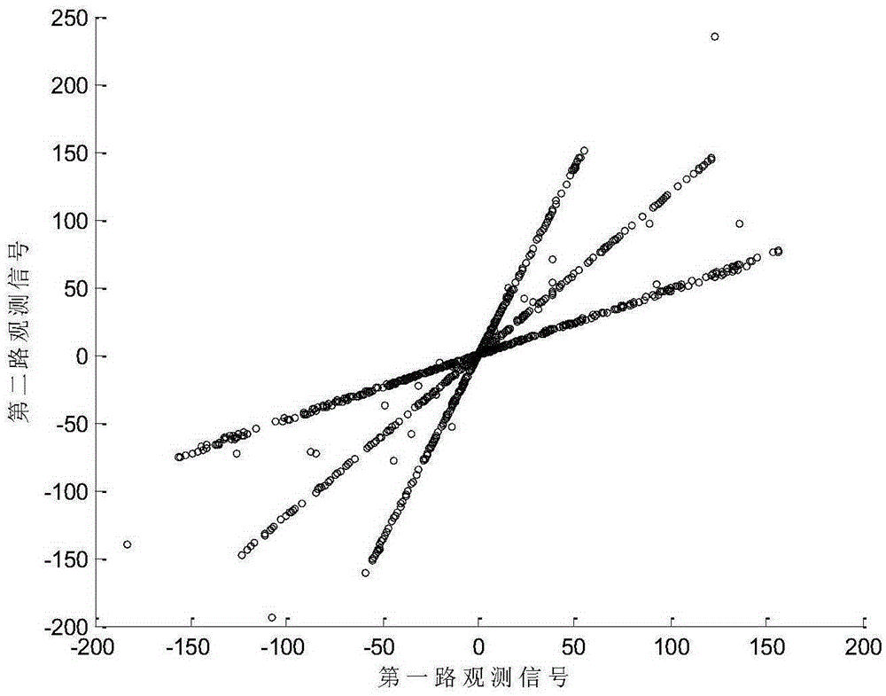
At the same time, no matter which method is used above, when the directions of any two column vectors of the mixing matrix are very close, that is, when the slopes of two straight lines in the straight line formed by the observed signal are very close and small due to the source signal, the estimation of the mixing matrix will be caused. produce a large error

Method used


Image

  • Mixing matrix estimation method aiming at underdetermined blind source separation
  • Mixing matrix estimation method aiming at underdetermined blind source separation
  • Mixing matrix estimation method aiming at underdetermined blind source separation

Examples


Embodiment Construction

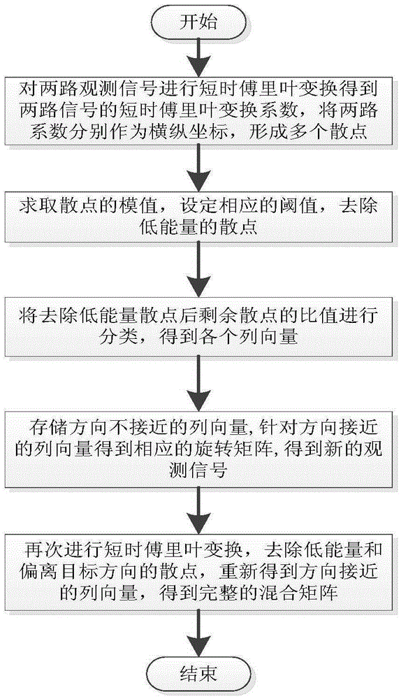
[0024] like figure 1 As shown, the hybrid matrix estimation method for underdetermined blind source separation of the present invention includes the following steps:

[0025] Step 1: Perform short-time Fourier transform on the received two observation signals respectively to obtain the short-time Fourier coefficients X of the two observation signals 1 (t,f) and X 2 (t,f) (t represents the observation time, f represents the frequency), the X 1 (t,f) and X 2 The corresponding values ​​of (t, f) are used as abscissa and ordinate respectively to form multiple scatter points.

[0026] Underdetermined blind separation in the case of linear instantaneous mixing can be represented by the following mathematical model:

[0027] x(t)=As(t)(1)

[0028] In the formula, s(t)=[s 1 (t),s 2 (t),...,s M (t)] T is the M-dimensional source signal vector, x(t)=[x 1 (t),x 2 (t),...,x N (t)] T is the N-dimensional observation signal vector, where M>N. t is the observation time, t=1,......


PUM


Abstract

The present invention relates to a mixing matrix estimation method aiming at underdetermined blind source separation. The method comprises: respectively performing short-time fourier transform on two paths of received observation signals to obtain short-time fourier coefficients X1 (t, f) and X2 (t, f) of two paths of observation signals, forming a plurality of scattered points and removing the low-energy scattered points; obtaining ratios of the remained scattered points, classifying the scattered points according to the ratios to obtain an M class with the largest number of scattered points, calculating an average value of the ratios of the scattered points in each class, then transforming each average value into a slope angle of a straight line, converting each slope angle into a column vector, obtaining a rotation matrix T according to the column vectors of which the directions are approximate, and performing rotation conversion to obtain two paths of new observation signals X'1 (t, f) and X'2 (t, f); and aiming at the two paths of observation signals X'1 (t, f) and X'2 (t, f) and according to a ratio of two paths of observation signals, classifying the scattered points to obtain an S class with a largest number of scattered points, calculating an average value of the ratios of the scattered points in each class, then obtaining an approximate slope angle, obtaining corresponding column vectors by the slope angles and finally, obtaining an integral mixing matrix.

Description

technical field [0001] The present invention relates to the technical field of blind signal processing, in particular to a hybrid matrix estimation method for underdetermined blind source separation. Background technique [0002] How to extract each single information from the information received by the sensor is called the problem of blind source separation, and the corresponding solution is called blind source separation technology. With the continuous research of domestic and foreign experts and scholars, blind source separation technology has gradually developed, and has been widely used in mechanical fault detection, communication signal processing, speech signal processing, image signal processing, biomedical engineering and other fields. According to the number of source signals and the number of observed signals, blind source separation problems can be divided into two types: underdetermined blind source separation problems and non-underdetermined blind source separ...

Claims


Application Information

Patent Timeline
IPC IPC(8): G06K9/62
CPCG06F18/2134
Inventor 李一兵聂伟王秋滢林云叶方王彦欢罗仁欢陈杰杜敏
Owner HARBIN ENG UNIV
Why Eureka
Eureka Blog
Learn More