
A laser light guide plate structure

A technology of light guide plate and laser, applied in the field of light guide plate, can solve the problems of inability to satisfy consumers, single brightness and color tone, etc., and achieve the effect of rich color tone

Active Publication Date: 2018-04-17
SUZHOU SUNSHINE LASER & ELECTRONICS TECH CO LTD
View PDF4 Cites 0 Cited by
  • Summary
  • Abstract
  • Description
  • Claims
  • Application Information

AI Technical Summary

Problems solved by technology

Existing light guide plates are usually monolithic and have a whole plate-like structure. The brightness of different areas on the light guide plate is the same, and the brightness and color tone are relatively single, which cannot meet the needs of consumers.

Method used

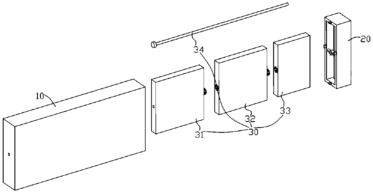

Image

  • A laser light guide plate structure
  • A laser light guide plate structure
  • A laser light guide plate structure

Examples


Embodiment

[0027] Examples: The following specific examples illustrate the implementation of the present invention, and those skilled in the art can easily understand other advantages and effects of the present invention from the content disclosed in this specification.

[0028] See figure 1 and figure 2 As shown, a laser light guide plate structure includes: a first housing 10 with an open end; the opening end installed on the first housing 10 and the first housing 10 are jointly surrounded to form a closed chamber The second housing 20; the light guide partition unit 30 installed in the first housing 10; and the light source 40 installed in the second housing 20. See figure 2 As shown, the light guide baffle unit 30 includes a bolt 34 penetrating through the side wall of the first housing 10 and a first light guide baffle 31 and a second light guide baffle that are sequentially sleeved on the bolt 34 . Plate 32 and the third light guide partition 33; see Figure 5 to Figure 7 As ...


PUM


Abstract

The invention discloses a laser light guide plate structure. The structure comprises a first casing cover with an open end, a second casing cover, a light guide separating plate unit and a light source, wherein the second casing cover is mounted at the open end of the first casing cover, the first casing cover and the second casing cover form an enclosed cavity, the light guide separating plate unit is mounted in the first casing cover, and the light source is mounted in the second casing cover. Via the structure, different areas of the a light guide plate are different in the brightness, tones are more richer, and the structure is beautiful and graceful.

Description

Technical field: [0001] The present invention relates to the technical field of light guide plates, and more specifically relates to a light guide plate structure. Background technique: [0002] The light guide plate is a plate that uses an optical grade acrylic plate, and then uses a high-tech material with high reflectivity and no light absorption to print light guide points on the bottom surface of the optical grade acrylic plate with UV screen printing technology. Existing light guide plates are generally integral, and have a monolithic plate-like structure. The brightness of different regions on the light guide plate is the same, and the brightness and color tone are relatively single, which cannot meet the needs of consumers. Invention content: [0003] The purpose of the present invention is to provide a laser light guide plate structure for the deficiencies of the prior art, which can achieve different brightness in different areas on the light guide plate, richer ...

Claims


Application Information

Patent Timeline
Patent Type & Authority Patents(China)
IPC IPC(8): G02B6/00
CPCG02B6/0011G02B6/0078G02B6/0088
Inventor 王荣惠国庆
Owner SUZHOU SUNSHINE LASER & ELECTRONICS TECH CO LTD
Learn More