Multi-layer and multi-stage pipe tunnel slide type veneer drying device

A drying device and pipe hole technology, which is applied in the direction of drying gas arrangement, heating device, drying chamber/container, etc., can solve the problems of inability to reduce equipment manufacturing cost, high equipment manufacturing cost and use cost, and more heat dissipation, and achieve favorable The effects of popularization and use, low cost of manufacturing equipment, and simple equipment structure

Inactive Publication Date: 2016-02-24
黄达宏
View PDF6 Cites 4 Cited by
  • Summary
  • Abstract
  • Description
  • Claims
  • Application Information

AI Technical Summary

Problems solved by technology

The former, such as drying room, tunnel drying line, etc., belong to this category. The disadvantages are large space occupation, high heat dissipation, slow speed and low efficiency.
The latter, such as multi-layer hot-press dryers, roller-type veneer dryers, etc., belong to this category. The advantage is that the drying speed of the monomer is fast, and the disadvantage is that the energy consumption is high, and the equipment manufacturing cost and use cost are high.
No matter whether the former or the latter is used, it will consume a lot of labor, and it is impossible to save energy and labor, and it is impossible to reduce the cost of equipment manufacturing.

Method used


Image

  • Multi-layer and multi-stage pipe tunnel slide type veneer drying device
  • Multi-layer and multi-stage pipe tunnel slide type veneer drying device
  • Multi-layer and multi-stage pipe tunnel slide type veneer drying device

Examples


Embodiment

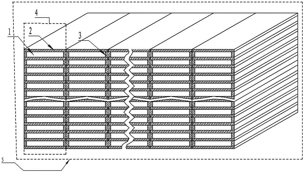
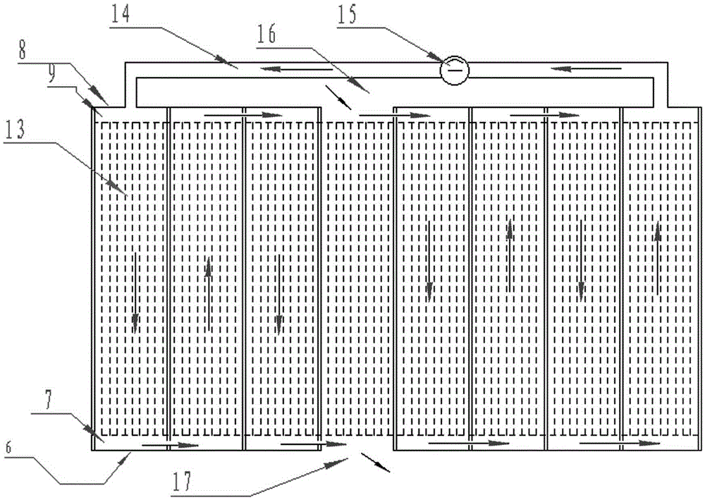
[0027] refer to Figure 1-4 , a 30-layer eight-stage pipe hole slide type veneer drying device, including a drying box (not shown in the figure), a heat-conducting oil boiler 18, a heat-conducting oil circulation pipeline 23 connecting the drying box and the heat-conducting oil boiler 18, and set in The circulating oil pump 20 on the pipeline is provided with a drying rack 5 in the drying box, and a heat insulation layer is also provided on the periphery of the drying box; the drying rack 5 is composed of two hundred and forty Eight heating plates 2 with embedded heating oil pipelines and two hundred and seventy load-bearing support partitions 3 arranged vertically and parallel to each other are constructed. There are 240 flat rectangular tube-shaped spaces in 30 floors and eight rows. This tube-shaped space is called the tube-hole drying room 1; the upper and lower surfaces of each tube-hole drying room 1 are respectively heating plates. 2, the left and right sides are respe...


PUM


Abstract

The invention discloses a multi-layer and multi-stage pipe tunnel slide type veneer drying device. The multi-layer and multi-stage pipe tunnel slide type veneer drying device comprises a drying box, a conduction oil boiler, a conduction oil circulating pipeline and a circulating pump, wherein the conduction oil circulating pipeline is connected with the drying box and the conduction oil boiler, and the circulating pump is arranged on the conduction oil circulating pipeline. A drying frame is arranged in the drying box, and a heat insulation layer is arranged on the periphery of the drying box. Being different from the prior art, the drying frame is formed by heating plates and bearing and supporting partition plates, wherein the heating plates are arranged in parallel in the quasi-horizontal direction, heating oil pipelines are buried in the heating plates, and the bearing and supporting partition plates are arranged in parallel in the vertical direction; a plurality of layers and a plurality of columns of flat rectangular pipe-tunnel-shaped spaces of the same specification are formed in the drying frame at equal intervals and in parallel and serve as pipe tunnel type drying chambers, and material enters or exits from the drying chambers in a sliding mode. The multi-layer and multi-stage pipe tunnel slide type veneer drying device has the advantages that the manpower and the electric energy are saved, the heat energy is reasonably recycled, the heat dissipation rate is low, it is difficult to catch fire but easy to extinguish fire, the structure is simple, the manufacturing cost is low, the investment is small, and use and popularization are convenient.

Description

technical field [0001] The invention relates to the field of heat energy application, in particular to a multi-layer and multi-stage pipe hole slide type veneer drying device which uses heat conduction oil for heat supply. technical background [0002] There is a process in wood processing: cutting the felled logs into certain specifications of raw wet wood chips, that is, veneers, and these veneers need to be dried for transportation, storage or further processing. Drying methods generally include sun drying and equipment drying. Existing drying equipment for drying veneers can be roughly divided into two categories: one is to transfer heat to the veneer through air flow, and the veneer obtains heat energy and evaporates water to dry. The other is to use heat conduction to transfer heat energy to the veneer through the contact between solids, and the veneer obtains heat energy, the temperature rises, and the water evaporates and dries. The former, such as drying room and ...

Claims


Application Information

Patent Timeline
Patent Type & Authority Applications(China)
IPC IPC(8): F26B9/06F26B23/02F26B21/00F26B25/14
Inventor 黄达宏
Owner 黄达宏
Why Eureka
Try Eureka