Eureka AIR delivers breakthrough ideas for toughest innovation challenges, trusted by R&D personnel around the world.

Mounting assembly of thermostat for gasoline engine

A technology for installing components and thermostats, which is applied in the direction of engine components, machines/engines, mechanical equipment, etc., and can solve problems such as the influence of thermostat and thermostat seat sealing, affecting the sealing performance of cooling water, and temperature sensor distortion , to achieve the effect of simple structure, accurate installation direction and guaranteed sealing

Active Publication Date: 2016-02-24
CHONGQING SOKON IND GRP CO LTD
View PDF9 Cites 1 Cited by
  • Summary
  • Abstract
  • Description
  • Claims
  • Application Information

AI Technical Summary

Problems solved by technology

When filling the engine with coolant, the temperature of the new thermostat seat is closed because the temperature of the thermostat seat does not meet the opening requirements, which may easily cause air accumulation in the water outlet chamber. When the temperature sensor is distorted, and the accumulated air will also affect the sealing of the joint surface between the thermostat and the thermostat seat; in addition, as a temperature control device, the thermostat has a certain directionality when installed. Even if there is an exhaust device on it, the exhaust direction is also directional. If the thermostat is installed in the wrong direction in the outlet chamber, not only will it not be able to regulate the waterway, but the exhaust will not proceed, which will affect the cooling waterway. Sealing performance

Method used


Image

  • Mounting assembly of thermostat for gasoline engine
  • Mounting assembly of thermostat for gasoline engine
  • Mounting assembly of thermostat for gasoline engine

Examples


Embodiment Construction

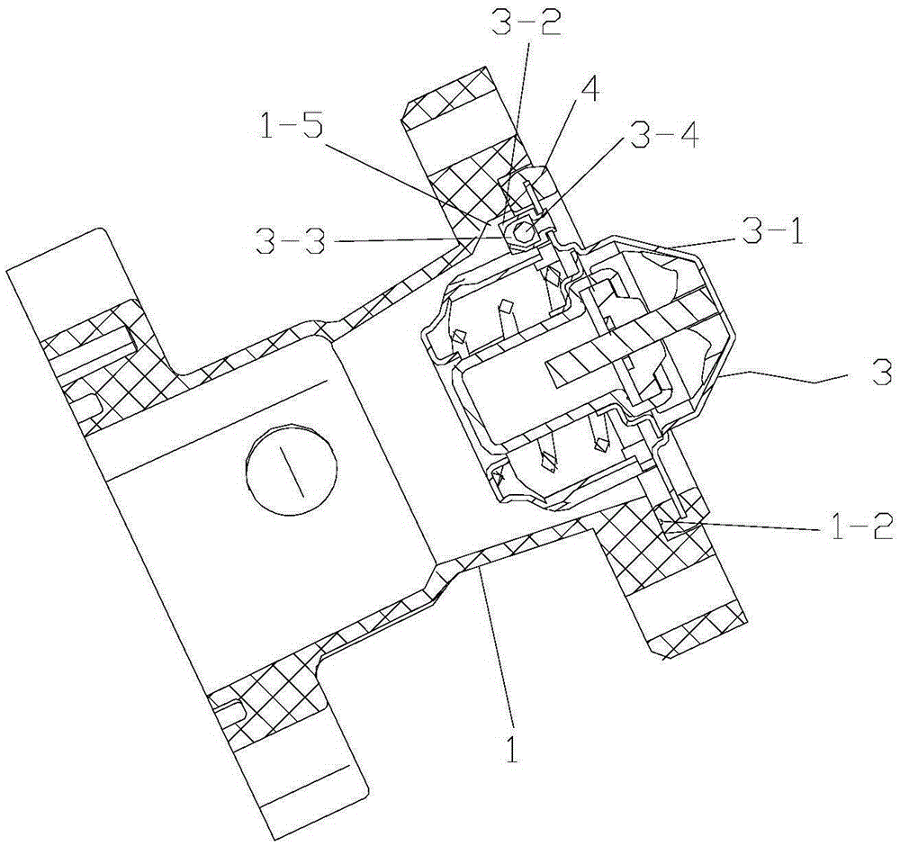
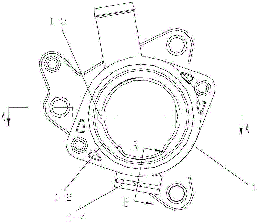
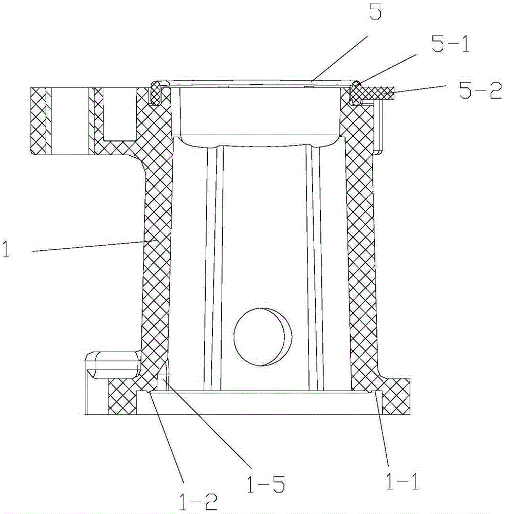
[0023] figure 1 It is a schematic diagram of the overall structure of the present invention, figure 2 It is a structural schematic diagram of the thermostat seat in the present invention, image 3 for figure 2 A-A direction view, Figure 4 for figure 2 B-B direction view, Figure 5 for figure 2 side view, Figure 6 for figure 2 Rear view, Figure 7 It is a structural schematic diagram of a thermostat in the present invention, Figure 8 It is a schematic diagram of the assembly of the overall structure of the present invention combined with the end cover of the thermostat, as shown in the figure: the engine thermostat of this embodiment includes a thermostat 3 and a thermostat seat 1, and the upper end of the thermostat seat 1 is formed for installation The valve seat 1-1 of the thermostat 3, the inner wall of the thermostat seat 3 close to the valve seat 1-1 is provided with a limit groove 1-5 for limiting the installation of the thermostat 3, and the thermostat ...


PUM


Abstract

The invention discloses a mounting assembly of a thermostat for a gasoline engine. The mounting assembly comprises the thermostat and a thermostat seat, wherein a valve seat for mounting the thermostat is formed at the upper end of the thermostat seat; a limiting groove is formed in the inner wall of the thermostat seat; the thermostat comprises an upper bracket, and a limiting block which is arranged on the upper bracket; an air exhausting channel in the limiting block and a ball body form an one-way air exhaust valve structure; the thermostat further comprises an outer sealing part; the end surface of the valve seat is upwards bulged to form a sealing rib which is in sealing fit with the outer sealing part. According to the mounting assembly of the thermostat for the gasoline engine, the limiting block and the limiting groove are matched to position to achieve limited mounting, so that the quick positioning mounting can be achieved; in addition, the mounting direction of the thermostat can be accurately determined, and thus the thermostat can be prevented from being reversely mounted; meanwhile, the one-way air exhaust valve structure is formed in the limiting block and can be used for exhausting air in a cooling water channel, so as to prevent the sealing from failure due to air accumulation; the bulged sealing rib arranged on the valve seat and the outer sealing part of the thermostat act together to form a maze sealing structure through which the sealing performance can be greatly improved.

Description

technical field [0001] The invention relates to an engine component, in particular to a thermostat installation assembly for a gasoline engine. Background technique [0002] The thermostat can adjust the water path entering the radiator according to the temperature of the cooling water in the engine, thereby changing the circulation path of the cooling water and adjusting the heat dissipation capacity of the cooling system to ensure that the engine works within a suitable temperature range. At present, the thermostat on the engine cooling system adopts wax type thermostat, which is mainly composed of brackets, valves, temperature sensing components, etc. An important factor in the normal operation of the thermostat. When filling the engine with coolant, the temperature of the new thermostat seat is closed because the temperature of the thermostat seat does not meet the opening requirements, which may easily cause air accumulation in the water outlet chamber. When the tempe...

Claims


Application Information

Patent Timeline
Patent Type & Authority Applications(China)
IPC IPC(8): F01P7/16F01P11/02F16J15/06
CPCF01P7/16F01P11/02F16J15/061F16J15/062
Inventor 段伟陈杰陈浩
Owner CHONGQING SOKON IND GRP CO LTD
Why Eureka
Eureka Blog
Learn More