
A differential pressure negative pressure automatic water release device

An automatic water discharge and differential pressure technology, which is applied in the direction of safety devices, drainage, gas discharge, etc., can solve problems such as blockage of drainage pipelines, workload cannot meet the discharge requirements of the water release device, and affect the drainage effect, etc., to prevent water leakage The effect of air leakage

Active Publication Date: 2017-10-03
NORTH CHINA INST OF SCI & TECH
View PDF7 Cites 0 Cited by
  • Summary
  • Abstract
  • Description
  • Claims
  • Application Information

AI Technical Summary

Problems solved by technology

However, the existing coal mine gas drainage efficiency is low and cannot meet the needs of use
The main reasons why it is difficult to improve the drainage efficiency are the problems of well pattern, hole sealing and water plugging.
Among them, the problem of water blockage is extremely prominent in the process of on-site drainage. During the drainage process, the liquid water and coal slime in the coal strata inevitably flow into the drainage pipeline by their own weight and negative pressure. Due to the temperature difference effect, the pipeline The gaseous water in the water will also condense into liquid water. The increase of the water volume will cause the local effective section of the drainage pipeline to become smaller, and even block the drainage pipeline, seriously affecting the drainage effect. The key equipment to solve the problem of water blockage is drainer
However, the existing coal mine drainage system is relatively large, and the number of drains is large. The workload of the ventilation team workers to repair the clogged drains cannot meet the discharge requirements of the drains, and cannot fundamentally solve the problem of gas pipeline drainage.

Method used


Image

  • A differential pressure negative pressure automatic water release device
  • A differential pressure negative pressure automatic water release device
  • A differential pressure negative pressure automatic water release device

Examples


Embodiment Construction

[0014] The present invention will be described in detail below in conjunction with the accompanying drawings and embodiments.

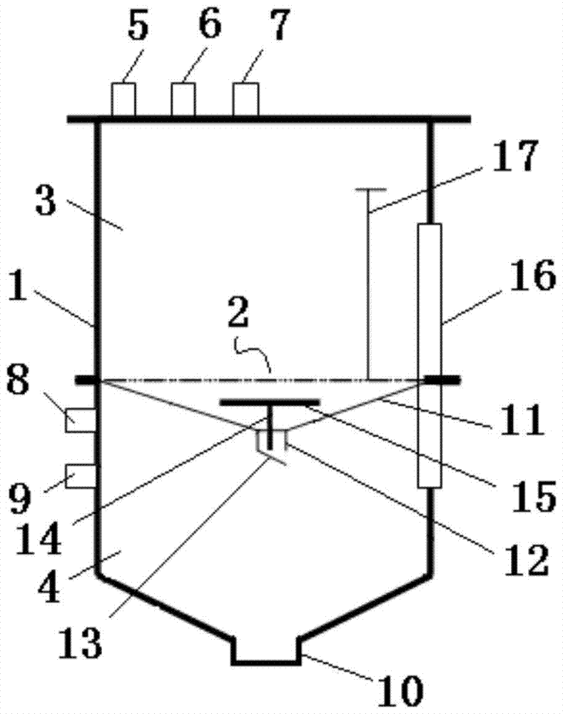
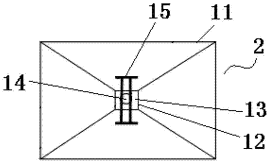
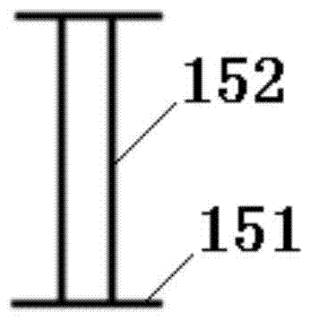
[0015] Such as figure 1 As shown, the present invention includes a tank body 1, and a partition device 2 arranged horizontally is fastened in the middle of the tank body 1. The partition device 2 divides the tank body 1 into an upper tank body 3 and a lower tank body 4 . A water inlet pipe 5 , a first negative pressure pipe 6 and a first negative pressure balance pipe 7 are arranged on the tank wall of the upper tank body 3 . A second negative pressure pipe 8 and a second negative pressure balance pipe 9 are arranged on the tank wall of the lower tank body 4 . A drainpipe 10 with a large diameter is arranged at the bottom of the tank body 1 . Such as figure 2 As shown, the partition device 2 includes a funnel-shaped partition 11, a drain 12 is provided at the center of the partition 11, a plug plate 13 is rotatably connected to the bottom of the ...


PUM


Abstract

The invention relates to a pressure difference type negative pressure automatic water drainage device which is characterized by comprising a tank body, wherein a separating device is connected in the tank body; the tank body is divided into an upper tank body and a lower tank body by the separating device; a water inlet pipe, a first negative pressure pipe and a first negative pressure balance pipe are arranged on the tank wall of the upper tank body; a second negative pressure pipe and a second negative pressure balance pipe are arranged on the tank wall of the lower tank body; a water drainage pipe is arranged at the bottom of the tank body; the separating device comprises an interlayer, and a water drainage opening is formed in the middle part of the interlayer; and a filling board is connected at the bottom of the water drainage opening in a rotating way, the filling board is connected with a guide frame through a spring, and the guide frame is tightly connected with the interlayer. According to the invention, the separating device is arranged in the tank body, the water inlet pipe, the first negative pressure pipe and the first negative pressure balance pipe are arranged on the upper tank body, the second negative pressure pipe and the second negative pressure balance pipe are arranged on the lower tank body, and the water drainage pipe is arranged at the bottom of the tank body, so that the pressure difference between the upper tank body and the lower tank body can be adjusted by opening and closing valves on all pipelines, and then water storage and water drainage of coal slime and water in the tank body are realized.

Description

technical field [0001] The invention relates to a water discharge device, in particular to a differential pressure negative pressure automatic water discharge device. Background technique [0002] Coal mine gas drainage is the use of gas pumps or other drainage equipment to extract the high volume fraction of gas in the coal seam, and discharge the extracted high volume fraction gas to the ground or the mine's total return airway through the pipe network isolated from the roadway. Coal mine gas drainage is not only an important measure to reduce mine gas emission and prevent gas explosion, but also the extracted gas can be developed and utilized as an associated resource of coal. However, the existing coal mine gas drainage efficiency is low, which cannot meet the needs of use. The main reasons why it is difficult to improve the drainage efficiency are the problems of well pattern, hole sealing and water plugging. Among them, the problem of water blockage is extremely prom...

Claims


Application Information

Patent Timeline
Patent Type & Authority Patents(China)
IPC IPC(8): E21F7/00E21F16/00
CPCE21F7/00E21F16/00
Inventor 陈学习李东明
Owner NORTH CHINA INST OF SCI & TECH
Learn More