
A mechanical lock of double-core mutual control trap-type blade mechanism

A technology of mechanical locks and blades, applied in the field of mechanical locks, can solve the problems of not being able to fall completely, unable to prevent technical unlocking or violent unlocking, and lock cylinder not being able to rotate, etc., to achieve the effect of improving safety and eliminating technical unlocking.

Active Publication Date: 2017-12-05
厦门天工创新科技发展有限公司
View PDF6 Cites 0 Cited by
  • Summary
  • Abstract
  • Description
  • Claims
  • Application Information

AI Technical Summary

Problems solved by technology

If one or more of the key grooves on the key do not match the combination of the blades, the grooves on the blades in the lock cylinder will not match the bottom of the tumbler, the tumbler will not fall completely, and the tumbler will not be released The clamping of the lock head body, in this way, the lock cylinder and the lock head body are connected through the tumbler, and the lock cylinder cannot be rotated
Although this lock of the prior art has better safety compared with the tumbler lock, it still cannot prevent technical unlocking or violent unlocking.

Method used


Image

  • A mechanical lock of double-core mutual control trap-type blade mechanism
  • A mechanical lock of double-core mutual control trap-type blade mechanism
  • A mechanical lock of double-core mutual control trap-type blade mechanism

Examples


Embodiment 1

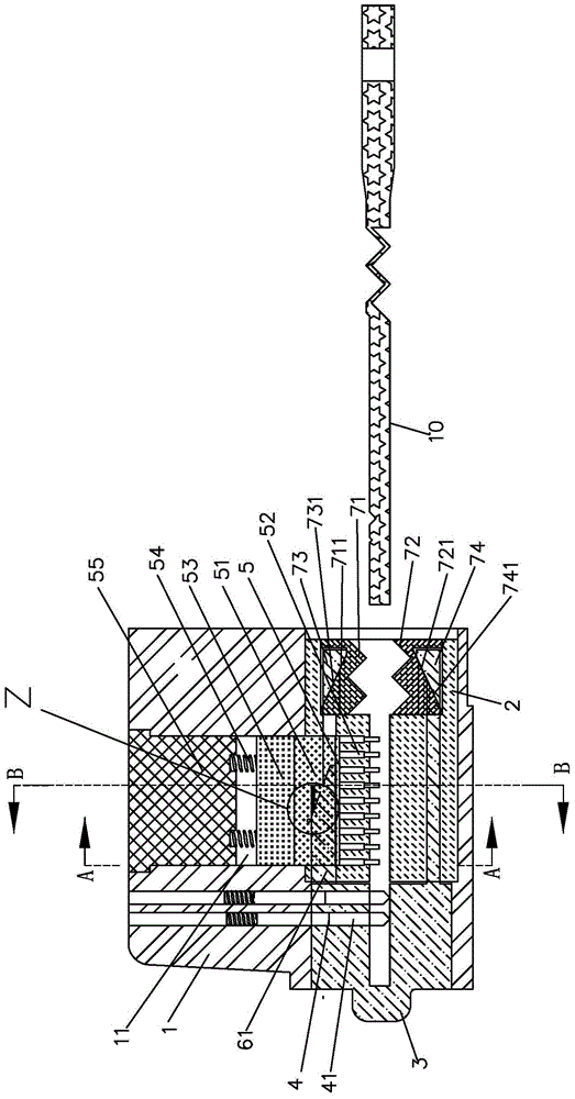
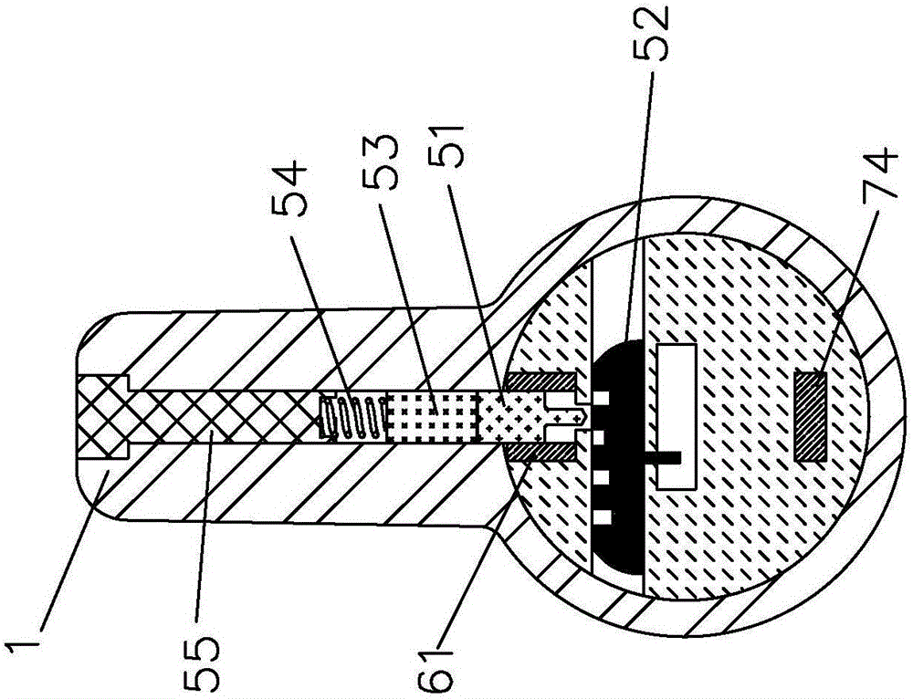
[0057] see Figure 1 to Figure 28 As shown, a mechanical lock of a dual-core mutual control trap-type blade mechanism of the present invention includes a lock head and a key 10; the lock head includes a lock head body 1, a front lock cylinder 2 and a rear lock cylinder 3; the front lock cylinder 1. The rear lock core is rotatably installed in the lock head body, and the rear lock core 3 can also move axially; the front lock core, the rear lock core and the lock head body are respectively equipped with a front locking mechanism 5 that can be decoded by a key 10 , the rear locking mechanism 4; the front locking mechanism 5 is a blade mechanism, the blade mechanism includes a tumbler 51 and a plurality of blades 52 for matching with the convex portion 512 at the bottom of the tumbler, and the blade 52 is provided with a plurality of blades Slot 521, in a plurality of blade grooves 521, only one blade groove 521 is the combination groove, and other blade grooves 521 are all trap g...

Embodiment 2

[0080] see Figure 29 As shown, the mechanical lock of a dual-core mutual control trap-type blade mechanism of the present invention is different from Embodiment 1 in that the rear locking mechanism 4 between the rear lock cylinder and the lock head body is a blade mechanism 42 , the blade mechanism 42 is installed between the rear lock core 3 and the lock body 1 in the radial direction to limit the rotation and axial movement of the rear lock core.


PUM


Abstract

The invention discloses a mechanical lock of a double-core mutual control trap type blade mechanism, which comprises a lock head body, front and rear lock cores, front and rear locking mechanisms, a gate and a key; the front locking mechanism is a blade mechanism, and the blade mechanism includes a The tumbler and at least one blade for mating with the bottom of the tumbler, the blade is provided with a combination slot and at least one trap slot; the rear lock cylinder is also equipped with a control mechanism for controlling the tumbler, and the rear lock cylinder is not moved in place. Front, the tumbler cannot fall; anti-rear locking mechanism decodes, when the rear lock cylinder moves backward along the axial direction, the tumbler falls, when the tumbler falls into the password slot of the blade, the front locking mechanism decodes, and the gate is closed at the same time, the front , The rear lock cylinder rotates together under the drive of the key to unlock; when the tumbler falls into the trap groove of the blade, the front locking mechanism is not decoded and the blade cannot move. The present invention adopts a new idea and a new method of exchanging position difference for time difference, and is one of the most effective prevention techniques and locksets for violent unlocking in the world at present.

Description

technical field [0001] The invention relates to a lock, in particular to a mechanical lock with a dual-core mutual control trap-type blade mechanism. Background technique [0002] A kind of lockset of prior art is to adopt leaf mechanism as locking mechanism, and this lockset usually comprises lock head body, lock core, tumbler, blade and key, and tumbler is arranged between lock head body and lock cylinder, usually Both the lock head body and the lock cylinder are provided with tumbler grooves, the tumblers can only move at the tumbler grooves of the lock head body and the lock cylinder, and when not unlocked, the tumblers are at the tumbler grooves of the lock head body Groove and the tumbler groove place of lock core, lock core can not be rotated relative to the lock head body, when unlocking, tumbler falls, and the lock core of this moment just can realize unblanking with respect to the lock head body rotation. The upper part of the blade of this lock is usually provide...

Claims


Application Information

Patent Timeline
Patent Type & Authority Patents(China)
IPC IPC(8): E05B31/00E05B19/08E05B15/00E05B15/14E05B15/02
Inventor 朱嘉斌
Owner 厦门天工创新科技发展有限公司
Learn More