
Automatic 45-degree poking device for short pins of LED stem conducting wire

A forty-five-degree, toggle device technology, applied to other household appliances, household appliances, applications, etc., can solve the problems of high labor intensity, high defective rate, and low efficiency of workers, so as to improve the efficiency of the foot-turning process, The effect of improving productivity

Active Publication Date: 2016-02-24
南通睿博电器有限公司
View PDF3 Cites 1 Cited by
  • Summary
  • Abstract
  • Description
  • Claims
  • Application Information

AI Technical Summary

Problems solved by technology

In this way, the efficiency is low, the labor intensity of the workers is high, and the defective rate is relatively high.

Method used


Image

  • Automatic 45-degree poking device for short pins of LED stem conducting wire
  • Automatic 45-degree poking device for short pins of LED stem conducting wire
  • Automatic 45-degree poking device for short pins of LED stem conducting wire

Examples


Embodiment 1

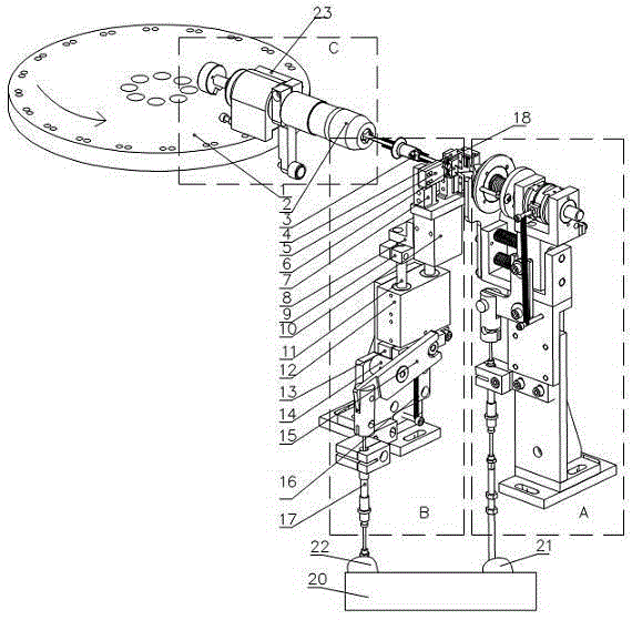
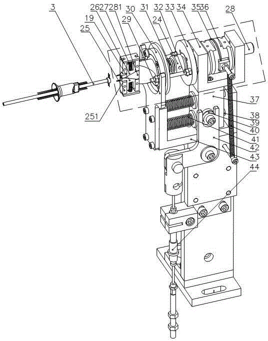
[0021] The main function of the short pin dialing 24 degree assembly of this device is to dial 4 short metal pins of the stem 3 into a shape of about 90 degrees mutually.

[0022] In the gap divider, the input shaft rotates continuously for one circle, and the output shaft can be used as a mechanism for stopping and rotating. The desired action can be completed during the stop period. The input shaft of the gap divider is connected with the motor through a belt, a reducer, a main shaft, and a sprocket chain.

[0023] As shown in Figure 1, the indexing disk has been reduced for the convenience of display. The indexing disk 1 is fixed on the output shaft end of the divider, and the gap divider, the short leg dial 24 degree mechanism (in the rectangular frame C) and the stem left and right positioning mechanism (in the rectangular frame B) are all fixed on the platen. Such as figure 1 , the stem is clamped in the stem clamp 2 (in the rectangular frame C), the upper stem clamp ...

Embodiment 2

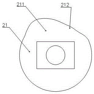
[0031] Such asfigure 1 As shown, the LED stem guide wire short leg automatic dialing device for 45 degrees is used to dial the four short metal legs connected to the stem 3 to make about 90 degrees to each other, including the connection on the indexing disc in turn. The clamping device 2, gap divider 23, stem positioning device and toggle device on 1; the stem positioning device and toggle device are respectively connected to the same transmission shaft 20 through a positioning and transmission cam 22, 21 for coordinated rotation , wherein: the stem positioning device: including the positioning chuck 5 concentric with the clamping device 2, the cylinder seat 8, the rail seat 9, the cylinder 10, the guide post 11, the positioning slider 12, the rail seat cam 13, the rocker arm 15, The thick pull wire 17, the cylinder 10 is connected in the cylinder block 8 to drive the positioning chuck 5 to clamp or loosen the core column 5; Provide support; the upper end of the rocker arm 15...


PUM


Abstract

The invention discloses an automatic 45-degree poking device for short pins of a stem conducting wire in automatic welding of an LED light bar. The device is characterized in that an upper pin poking tool and a lower pin poking tool which are symmetric to each other are sealed on a slide plate seat, wherein the upper pin poking tool and the lower pin poking tool are pushed through a pushing rod with a pushing sharp needle to move toward four short metal pins of a stem so as to bend the short metal pins. To achieve the aforementioned purpose, a shifting fork, a gap adjusting device, a spring wheel, a fine pulling line, a transmission rocker arm, a thick pulling line, a transmission cam and a transmission shaft are sequentially connected to the pushing rod, and a poking tool device and a positioning device are mutually coordinated and interconnected to work, so as to achieve full-automatic 45-degree poking of the short pins of the stem. With the adoption of the device, the efficiency of a pin poking process in an LED light bar welding technology can be improved; the pins can be automatically poked, so that the production efficiency can be improved.

Description

technical field [0001] The invention relates to the technical field of LED lamp strip processing, in particular to a device for automatically turning the short legs of LED stem guide wires to 45 degrees. Background technique [0002] At present, in the existing LED light strip welding technology, a fully manual or semi-automatic production method is usually adopted, and the metal wire shaping and soldering process of the stem is manually performed, because it is required to adjust the metal long legs and short legs according to the angle. Pull apart, straighten, bend corners, etc., so as to meet the welding technical requirements of LED lights. Pulling apart and bending corners are usually done manually, or with small plastic jigs. In this way, the efficiency is low, the labor intensity of the workers is high, and the defective rate is relatively high. Contents of the invention [0003] In order to overcome the deficiencies of the above-mentioned prior art, the present i...

Claims


Application Information

Patent Timeline
Patent Type & Authority Applications(China)
IPC IPC(8): B21F1/00B21F45/00
CPCB21F1/00B21F45/00
Inventor 张小强韦晨
Owner 南通睿博电器有限公司
Learn More