LED driver circuit

A technology of light emitting diodes and driving circuits, which is applied in the layout of electric lamp circuits, light sources, electric light sources, etc., can solve the problems of inability to provide stable current for light emitting diodes, and achieve the effect of improving operating efficiency, improving stability, and stabilizing light emission.

Active Publication Date: 2018-07-17
ELITE SEMICON MEMORY TECH INC +1
View PDF4 Cites 0 Cited by
  • Summary
  • Abstract
  • Description
  • Claims
  • Application Information

AI Technical Summary

Problems solved by technology

Since each transistor shipped from the factory will have a different threshold voltage, the known LED drive circuit cannot provide a stable current to the LED without accurately knowing the characteristics of the transistor in advance.

Method used


Image

  • LED driver circuit
  • LED driver circuit
  • LED driver circuit

Examples


Embodiment Construction

[0034] Certain terms are used in the specification and subsequent claims to refer to particular elements. It should be understood by those skilled in the art that hardware manufacturers may use different terms to refer to the same components. This description and subsequent patent applications do not use the difference in name as a way to distinguish components, but use the difference in function of components as a criterion for distinguishing. The "comprising" mentioned throughout the specification and the following claims is an open-ended term, so it should be interpreted as "including but not limited to". In addition, the term "coupled" herein includes any direct and indirect means of electrical connection. Therefore, if it is described that a first device is coupled to a second device, it means that the first device may be directly electrically connected to the second device, or indirectly electrically connected to the second device through other devices or connection mea...


PUM


Abstract

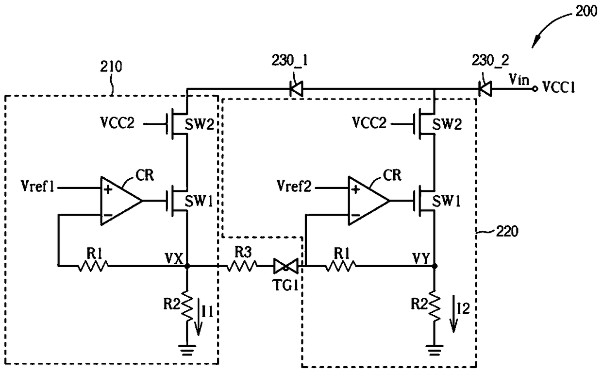
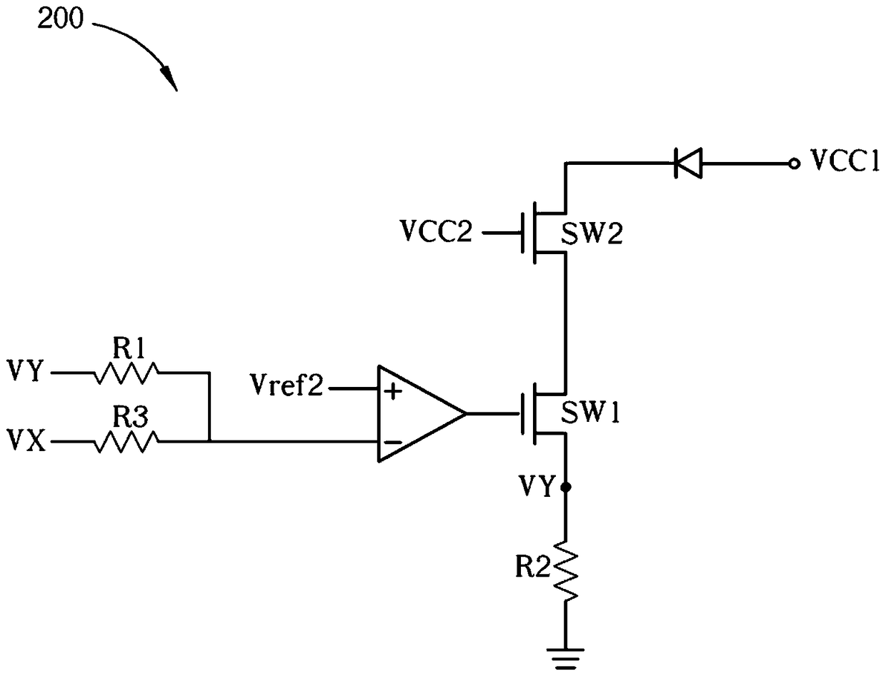
A light emitting diode driving circuit comprises a voltage source, a plurality of current control circuits, at least one third resistor and at least one transmission gate, wherein the voltage source is used for providing an input voltage, each current control circuit comprises a first switch, a comparator, a first resistor and a second resistor, the first switch is coupled to a corresponding group of light emitting diodes, the comparator is coupled to a corresponding reference voltage and the switch, the first resistor is coupled to the comparator and the first switch, the second resistor is coupled to the first switch and a common reference voltage, the third resistor is coupled to the first switch of one of the current control circuits, and the transmission gate is coupled between the third resistor and the comparator of another current control circuit of the plurality of current control circuits.

Description

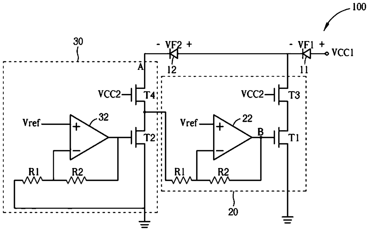
technical field [0001] The invention relates to a light emitting diode driving circuit, in particular to a light emitting diode driving circuit for improving current stability. Background technique [0002] In order to save energy, lighting devices using light emitting diodes (light emitting diodes, LEDs) have become more and more popular. Generally, an LED device includes a plurality of LEDs to provide a desired luminance. A plurality of LEDs can be arranged in parallel or in series, or a mixture of the two. Regardless of the configuration, for the LED device, the correct voltage and / or current is provided to the LED for the LED. Operationally it is quite important. [0003] However, the existing LED drive circuit cannot provide a stable current, please refer to figure 1 , figure 1 It is a schematic diagram of a light-emitting diode driving circuit in the known technology. Such as figure 1 As shown, the LED driving circuit 100 includes multiple groups of LEDs (such as...

Claims


Application Information

Patent Timeline
Patent Type & Authority Patents(China)
IPC IPC(8): H05B37/02
Inventor 许哲玮梁伟成
Owner ELITE SEMICON MEMORY TECH INC
Why Eureka
Try Eureka