
Charging pile locking mechanism

A locking mechanism and charging pile technology, applied in the direction of collectors, electric vehicles, electrical components, etc., can solve the problems of inability to pull out the charging gun, equipment damage, safety accidents, etc., and achieve easy procurement, low malfunction rate, and circuit work. Stable and reliable effect

Inactive Publication Date: 2016-02-17
罗继东
View PDF6 Cites 3 Cited by
  • Summary
  • Abstract
  • Description
  • Claims
  • Application Information

AI Technical Summary

Problems solved by technology

[0002] Pulling out the charging gun during the charging of the electric vehicle by the charging pile will cause a safety accident, causing casualties, equipment damage and even fire. In order to avoid safety accidents, the charging gun needs to be locked during the charging process. , unlock after charging is complete; if the power is cut off during the charging process, the charging gun will not be able to be pulled out, and manual unlocking requires charging pile maintenance personnel to operate, which brings inconvenience to practical applications

Method used


Image

  • Charging pile locking mechanism
  • Charging pile locking mechanism

Examples


Embodiment Construction

[0016] The present invention will be further described below in conjunction with drawings and embodiments.

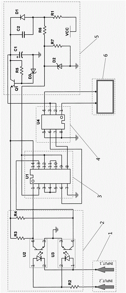
[0017] Such as figure 1 As shown, a charging pile locking mechanism includes a control signal input module 1 , an optocoupler isolation module 2 , a signal processing module 3 , a driving module 4 , a power sampling module 5 and a locking mechanism module 6 . Control signal input module 1 is connected to optocoupler isolation module 2, optocoupler isolation module 2 is connected to signal processing module 3, signal processing module 3 is connected to drive module 4, drive module 4 is connected to locking mechanism module 6, optocoupler isolation module 2 and signal processing module 3 and the drive module 4 are connected to the power sampling module 5; the optocoupler isolation module 2 isolates the control signal received by the control signal input module 1 and then inputs it to the signal processing module 3, and outputs it to the drive module 4 after being proces...


PUM


Abstract

The invention relates to a charging pile locking mechanism comprising a control signal input module, an optocoupler isolating module, a signal processing module, a driving module, a power sampling module and a locking mechanism module, wherein the control signal input module is connected with the optocoupler isolating module, the optocoupler isolating module is connected with the signal processing module, the signal processing module is connected with the driving module, the driving module is connected with the locking mechanism module, and the optocoupler isolating module, the signal processing module and the driving module are connected with the power sampling module; and the optocoupler isolating module isolates a control signal received by the control signal input module and then inputs the control signal to the signal processing module, then the control signal is processed by the signal processing module and then is output to the driving module, and the driving module performs current amplification and then drives the locking mechanism module so as to control the locking mechanism to lock and unlock a charging gun plugged into a charging pile.

Description

technical field [0001] The invention relates to a charging pile locking mechanism. Background technique [0002] Pulling out the charging gun during the charging of the electric vehicle by the charging pile will cause a safety accident, causing casualties, equipment damage and even fire. In order to avoid safety accidents, the charging gun needs to be locked during the charging process. , unlock after charging is complete; if the power is cut off during the charging process, the charging gun will not be pulled out, and manual unlocking requires charging pile maintenance personnel to operate, which brings inconvenience to practical applications. [0003] In order to ensure the safe and convenient charging of electric vehicles, the charging pile locking mechanism is required to lock the charging gun during charging, unlock after charging, and unlock when the charging pile is accidentally powered off. Contents of the invention [0004] Aiming at the deficiencies in the locki...

Claims


Application Information

Patent Timeline
Patent Type & Authority Applications(China)
IPC IPC(8): H02J7/00
Inventor 罗继东
Owner 罗继东
Learn More