
Tool and method for realizing charged replacement of tension insulator of extra-high voltage earth electrode line

A technology of strain insulators and live replacement, which is applied in the direction of overhead lines/cable equipment, etc., can solve the problems that workers cannot be protected from high temperature and high voltage damage, and the operation is cumbersome, so as to avoid long-term contact with high-temperature wires and protect personal safety. Safe, simple structure effect

Inactive Publication Date: 2016-02-17
国网河南省电力公司超高压公司 +1
View PDF8 Cites 6 Cited by
  • Summary
  • Abstract
  • Description
  • Claims
  • Application Information

AI Technical Summary

Problems solved by technology

[0006] In view of this, the purpose of the present invention is to address the deficiencies of the prior art, to provide a tool and method for live replacement of the tension insulator string of the UHV grounding electrode line, which solves the cumbersome operation of the prior art and the inability to ensure that the operators are free from The problem of being damaged by high temperature and high voltage

Method used


Image

  • Tool and method for realizing charged replacement of tension insulator of extra-high voltage earth electrode line
  • Tool and method for realizing charged replacement of tension insulator of extra-high voltage earth electrode line
  • Tool and method for realizing charged replacement of tension insulator of extra-high voltage earth electrode line

Examples


Embodiment 1

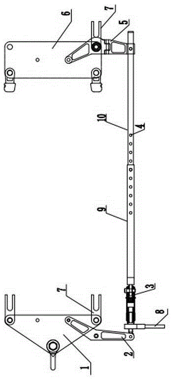
[0035] Such as figure 1 As shown, the tool of the present invention includes a front clamping part 2 , a lead screw 3 , an insulating puller and a rear clamping part 5 . The front clamping part 2 adopts a bent plate clamp, and the front clamping part 2 and one end of the lead screw 3 are fastened and connected by bolts; the insulating pull plate includes a fixing plate 9 and an adjusting plate 10, the fixing plate 9 adopts a hollow structure, and the size of the adjusting plate 10 is smaller than The fixed plate 9 and the adjustable plate 10 can be operated in and out of the fixed plate 9, and the adjustable plate 10 and the fixed plate 9 are uniformly provided with adjustment holes 4; the other end of the lead screw 3 and one end of the fixed plate 9 in the insulating pull One end of the adjustment plate 10 in the insulating pull plate is connected to the rear clamping portion 5 by bolts.

[0036]When in use, the front clamping part 2 is fixedly connected to the triangular c...

Embodiment 2

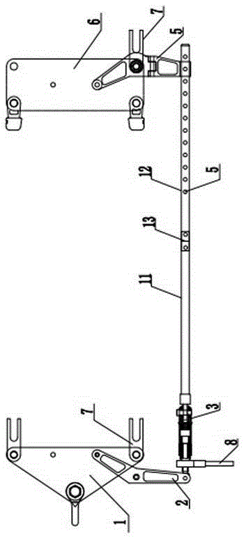
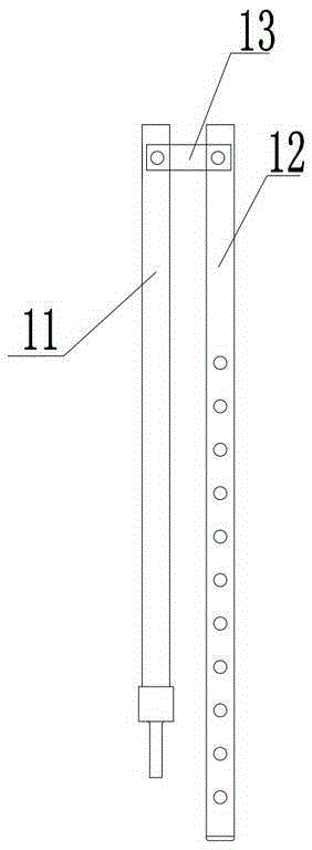
[0038] Such as figure 2 As shown, the tool of the present invention includes a front clamping part 2 , a lead screw 3 , an insulating puller and a rear clamping part 5 . The front clamp part 2 adopts a bent plate clamp, and the front clamp part 2 and one end of the lead screw 3 are fastened and connected by bolts; the insulating pull plate includes a first insulating pull plate 11, a second insulating pull plate 12 and a connecting part 13, and the first insulating pull plate 12 The pull plate 11 and the second insulating pull plate 12 are all installed on the connecting portion 13 through the rotating shaft, and the structure of the insulating pull plate when the insulating pull plate is unfolded is as follows: figure 2 As shown, the folded structure of the insulating pull plate is as follows image 3 As shown, one end of the second insulating pull plate 12 is uniformly provided with an adjustment hole 4; the other end of the lead screw 3 is fastened to the first insulatin...


PUM


Abstract

The invention discloses a tool for realizing charged replacement of a tension insulator of an extra-high voltage earth electrode line and a method for realizing charged replacement of the tension insulator of the extra-high voltage earth electrode line. The tool comprises a front blocking part, a screw, an insulation pulling plate and a rear blocking part, wherein the front blocking part utilizes a bending plate card and is connected with one end of the screw, the other end of the screw is connected with one end of the insulation pulling plate, the other end of the insulation pulling plate is connected with the rear blocking part, the length of the insulation pulling plate is adjustable, and adjusting holes are uniformly distributed on the insulation pulling plate; when the tension insulator is replaced by the tool, the body position of an electrician can not exceed a first tension insulator at the side of a cross arm, the minimum distance is 0.6m, another electrician on ground utilizes a temperature measurement instrument to detect the surface temperature of a wire, once the temperature continues to raise to be more than 60 DEG C, the electrician on ground needs to warn a No.2 electrician at the equipotential position timely, thereby avoiding personal injury caused by long-time contact to the high-temperature wire and ensuring personal safety of operators.

Description

technical field [0001] The invention relates to the field of electric power construction, in particular to a tool and a method for live replacement of tension insulators of UHV grounding pole lines. Background technique [0002] my country's energy has three major characteristics: a large amount of energy, a small amount per capita, and unbalanced regional distribution. The UHV DC transmission technology can meet the long-distance and large-capacity power supply needs. The DC transmission system has two operation modes: unipolar operation mode and bipolar operation mode. The unipolar operation mode is divided into metal loop mode and earth (or Seawater) as the single-pole ground loop mode of the circuit, when operating in the single-pole ground loop mode, the whole system current flows through the ground loop; under normal conditions for bipolar lines, only the unbalanced current flows through the ground loop (the value is about 1% of the rated current), but when a wire or ...

Claims


Application Information

Patent Timeline
Patent Type & Authority Applications(China)
IPC IPC(8): H02G1/02
Inventor 陶留海杨朝锋张建辉赵龙刘阔杨东辉高昆鹏李雪奎马志李瑞鹏靳航韩旭刘琦兰帅峰唐盼
Owner 国网河南省电力公司超高压公司
Learn More