
Professional mechanical device for grinding guide rail

A technology of professional machinery and guide rails, which is applied in the field of special abrasive mechanical devices, can solve the problems of low grinding precision and high labor intensity of personnel, and achieve the effects of high processing accuracy, reduced labor intensity of workers and long service life

Inactive Publication Date: 2016-02-17
刘兆财
View PDF0 Cites 0 Cited by
  • Summary
  • Abstract
  • Description
  • Claims
  • Application Information

AI Technical Summary

Problems solved by technology

[0003] The purpose of this invention is to solve the problems of high labor intensity and low grinding precision, and specially provides a professional mechanical device for grinding guide rails.

Method used


Image

  • Professional mechanical device for grinding guide rail

Examples


Embodiment 1

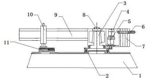
[0012] This embodiment provides a professional mechanical device for grinding guide rails, which is characterized in that: the professional mechanical device for grinding guide rails includes a base (1), fixing bolts (2), a main shaft (3), Motor (4), reducer (5), load-bearing rod (6), counterweight (7), fastening nut (8), beam (9), grinding head (10), guide rail (11);

[0013] Among them: the motor (4) and the reducer (5) are connected and installed on the beam (9), the right end of the beam (9) is welded with a load-bearing rod (6), and the load-bearing rod (6) is used to install the counterweight (7 ), the main shaft (3) is vertically welded with the beam (9), the grinding head (10) is installed on the beam (9), and the guide rail (11) is supported by the base (1).

[0014] The material of the beam (9) is high wear-resistant material.


PUM


Abstract

A professional mechanical device for grinding a guide rail is characterized in that the professional mechanical device for grinding the guide rail comprises a base, fixing bolts, a spindle, a motor, a speed reducer, a bearing rod, a balancing weight, a fastening nut, a walking beam, a grinding head and a guide rail; the motor and the speed reducer are connected to and mounted on the walking beam; the bearing rod is welded to the right end of the walking beam; the balancing weight is arranged on the bearing rod; the spindle and the walking beam are vertically welded; the grinding head is arranged on the walking beam; and the guide rail is supported by the base. The professional mechanical device for grinding the guide rail has the beneficial effects that machining precision is high, the labor intensity of workers is lowered, and economical usability is improved.

Description

technical field [0001] The invention relates to the field of a special abrasive mechanical device, and in particular provides a professional mechanical device for grinding guide rails. Background technique [0002] In the current vertical lathe industry, the contact uniformity between the workbench and the base guide rail has a great influence on the machining accuracy of the workpiece, and it also requires high flatness of the guide rail surface. The processing method of the guide rail surface has a great impact on reducing the labor of workers Intensity has a direct impact on improving work efficiency. At present, the processing of the guide rail plate is first processed on a milling machine, and then installed on the guide rail of the vertical lathe base. To meet the use requirements, but in this process, because the guide rail plate is milled, the surface accuracy is not high. In the process of cooperating with the shoveling, the amount of shoveling is relatively large, ...

Claims


Application Information

Patent Timeline
Patent Type & Authority Applications(China)
IPC IPC(8): B24B7/14
Inventor 刘兆财
Owner 刘兆财
Learn More