
Concave polygon region observation system automatic full coverage quick layout method

A concave polygon and observation system technology, applied in the direction of measuring devices, geophysical measurements, instruments, etc., to achieve the effect of improving rolling layout efficiency and inflection point accuracy, improving observation system design efficiency, and increasing speed

Active Publication Date: 2016-02-10
CHINA PETROLEUM & CHEM CORP +1
View PDF4 Cites 5 Cited by
  • Summary
  • Abstract
  • Description
  • Claims
  • Application Information

AI Technical Summary

Problems solved by technology

[0004] The purpose of the present invention is to solve the problems existing in the above-mentioned prior art, provide a method for automatic full-coverage rapid deployment of the observation system in a concave polygonal area, and solve the problem of automatic full-coverage rapid deployment of the three-dimensional observation system in the case of complex deployment boundaries, so that Technicians get rid of the inconvenience caused by manually designing the position of each beam of detector lines, and improve the rolling layout efficiency and inflection point accuracy of complex boundary cell templates

Method used


Image

  • Concave polygon region observation system automatic full coverage quick layout method
  • Concave polygon region observation system automatic full coverage quick layout method
  • Concave polygon region observation system automatic full coverage quick layout method

Examples


Embodiment Construction

[0069] Below in conjunction with accompanying drawing, the present invention is described in further detail:

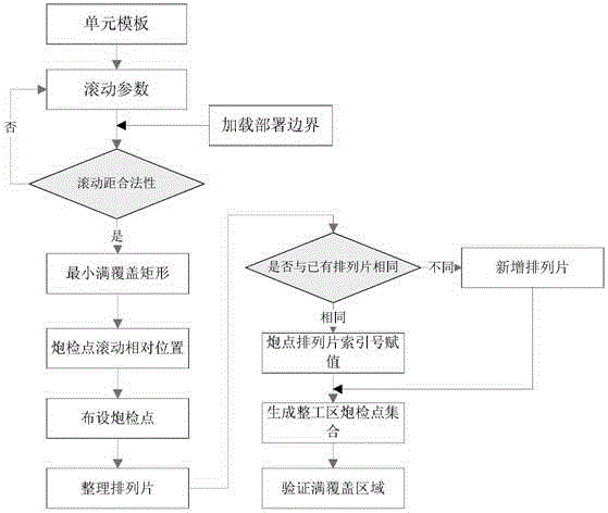
[0070] Such as figure 1 As shown, this method is specifically as follows:

[0071] (1) Create a unit template

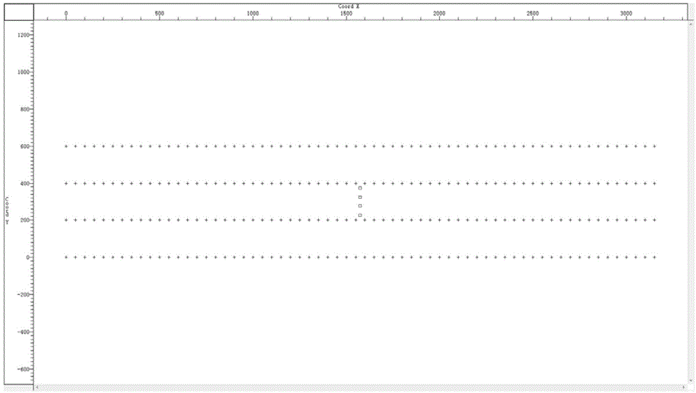
[0072] Before the design of the 3D observation system, it is necessary to define the parameters of the unit template according to the geological exploration tasks of the work area, that is, to define the relationship arrangement slices corresponding to the shot points. Unit template definition parameters include: number of detection lines, number of detection points, trace distance, detection line distance, start coordinates of detection points, number of shot lines, number of shot points, shot point distance, shot line distance, and shot point start coordinates. (Such as figure 2 shown)

[0073] (2) Establish rolling parameters and concave polygon deployment boundaries

[0074] Rolling parameters include: rolling azimuth, rolling distance along the su...


PUM


Abstract

The invention provides a concave polygon region observation system automatic full coverage quick layout method, which belongs to the field of seismic exploration and development. The method comprises the steps that (1) a unit template is established, wherein the unit template comprises the parameters of the number of detection lines, the number of detection points, track pitch, detection line pitch, detection point starting coordinates, the number of shot lines, the number of shot points, shot point pitch, shot line pitch and shot point starting coordinates; (2) rolling parameters and a concave polygon deployment boundary are established, wherein the rolling parameters comprises rolling azimuth, inline direction rolling pitch, x-line direction rolling pitch, and the deployment boundary is composed of a one-dimensional array and comprises all inflection point coordinates of the boundary, namely (x, y); and (3) a minimum full coverage region rectangle is calculated. According to the step (3), the minimum number of times of rolling in inline direction and the minimum number of times of rolling in x-line direction are calculated through the parameters of the unit template and the rolling parameters, wherein the minimum numbers of times are needed by unit template rolling layout to reach full coverage.

Description

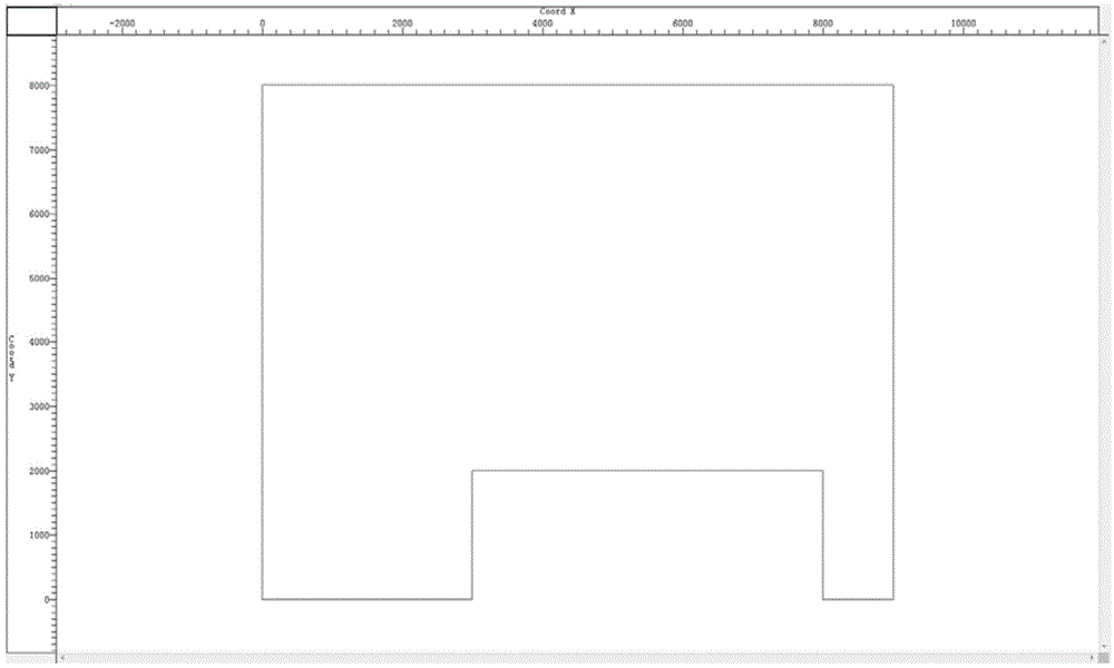
technical field [0001] The invention belongs to the field of seismic exploration and development, and in particular relates to an automatic full-coverage rapid deployment method for an observation system in a concave polygonal area. Background technique [0002] With the rapid development of oil exploration and development technology, the application of high-density 3D seismic exploration is increasing, domestic exploration blocks are gradually transitioning from simple surface conditions to complex surface conditions such as piedmont zone, and the geological tasks provided by the target work area The deployment boundary of the project is becoming more and more complex. For example, the deployment boundary of the Chengdu 3D seismic survey project deployed and implemented by Sinopec in the Chengdu area from 2011 to 2012 was in the shape of a concave polygon (such as figure 2 ), there are as many as 50 inflection point coordinates, and the full coverage area reaches more than ...

Claims


Application Information

Patent Timeline
Patent Type & Authority Applications(China)
IPC IPC(8): G01V1/00G01V1/20
Inventor 王昀
Owner CHINA PETROLEUM & CHEM CORP
Learn More