
Hydraulic independent heat dissipation control method, device and system

A cooling system, hydraulic technology, applied in the direction of fluid pressure actuation device, fluid pressure actuation system components, mechanical equipment, etc., can solve the problems of slow response speed of cooling system and inaccurate response results.

Active Publication Date: 2016-02-10
ZOOMLION HEAVY IND CO LTD
View PDF10 Cites 9 Cited by
  • Summary
  • Abstract
  • Description
  • Claims
  • Application Information

AI Technical Summary

Problems solved by technology

[0005] The embodiment of the present invention provides a hydraulic independent heat dissipation control method, device and system to at least solve the problem of controlling the electromagnetic proportional pressure reducing valve of the cooling pump to adjust the pump discharge of the cooling pump through the change of the hydraulic oil temperature in the existing hydraulic independent heat dissipation system. When measuring, the technical problem that the cooling system responds slowly to the change of hydraulic oil temperature and the response result is inaccurate due to the hysteresis phenomenon

Method used


Image

  • Hydraulic independent heat dissipation control method, device and system
  • Hydraulic independent heat dissipation control method, device and system
  • Hydraulic independent heat dissipation control method, device and system

Examples


Embodiment 1

[0021] According to an embodiment of the present invention, an embodiment of a method for controlling hydraulic independent heat dissipation is provided. It should be noted that the steps shown in the flowcharts of the accompanying drawings can be executed in a computer system such as a set of computer-executable instructions, and , although a logical order is shown in the flowcharts, in some cases the steps shown or described may be performed in an order different from that shown or described herein.

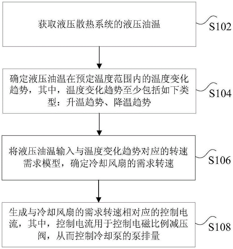
[0022] figure 2 It is a flow chart of the hydraulic independent heat dissipation control method according to Embodiment 1 of the present invention, as shown in figure 2 As shown, the method includes the following steps:

[0023] Step S102, acquiring the hydraulic oil temperature of the hydraulic cooling system.

[0024] As an optional embodiment, a temperature sensor may be used to detect the hydraulic oil temperature.

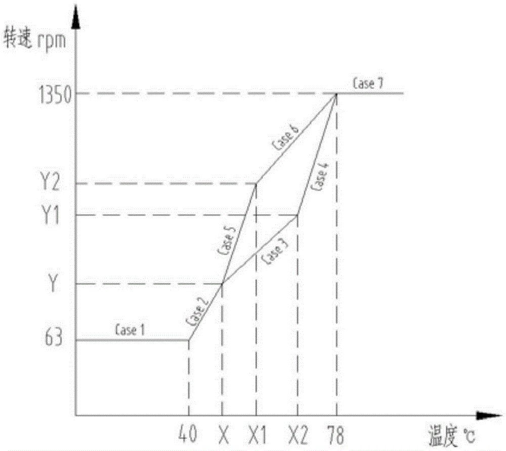
[0025] Step S104, determining the temperature change...

Embodiment 2

[0080] According to an embodiment of the present invention, an embodiment of a hydraulic independent heat dissipation control device is also provided.

[0081] Figure 5 is a schematic structural diagram of a hydraulic independent heat dissipation control device according to Embodiment 2 of this law.

[0082] Such as Figure 5 As shown, the device for acquiring push data may include: a first acquiring module 50 , a first determining module 52 , an input module 54 and a generating module 56 .

[0083] The first acquiring module 50 is configured to acquire the hydraulic oil temperature of the hydraulic cooling system.

[0084] The first determination module 52 is configured to determine a temperature change trend of the hydraulic oil temperature within a predetermined temperature range, wherein the temperature change trend includes at least the following types: a temperature rise trend and a temperature drop trend.

[0085] Specifically, in the above-mentioned device, the pre...

Embodiment 3

[0130] According to an embodiment of the present invention, a hydraulic independent heat dissipation control system is also provided, such as Figure 6 As shown, the system may include: a cooling pump 1, a cooling fan 4, an electromagnetic proportional pressure reducing valve 2, a hydraulic oil temperature sensor and a controller, wherein,

[0131] Cooling pump 1.

[0132] Cooling fan 4.

[0133] Specifically, such as Figure 6 As shown, in the above system, the cooling fan 4 is connected with the cooling motor 3 and rotates according to the control of the cooling motor to reduce the temperature of the hydraulic oil.

[0134] The electromagnetic proportional pressure reducing valve 2 is connected with the cooling pump 1 and is used to control the pump displacement of the cooling pump.

[0135] Specifically, such as Figure 6 As shown, in the above system, the electromagnetic proportional pressure reducing valve 2 is connected with the cooling pump 1 to control the pump dis...


PUM


Abstract

The invention discloses a hydraulic independent heat dissipation control method, device and system. The method includes the steps that the hydraulic oil temperature of a hydraulic heat dissipation system is obtained; temperature variation trends of the hydraulic oil temperature in a preset temperature range is determined, wherein the temperature variation trends at least comprise the temperature increasing trend and the temperature decreasing trend; the hydraulic oil temperature is input to a rotating speed requirement model corresponding to the temperature variation trends, and the required rotating speed of a cooling fan is determined; and a control current corresponding to the required rotating speed of the cooling fan is generated, the control current is used for controlling an electromagnetic proportional pressure reducing valve, and therefore the pump displacement of a cooling pump is controlled. Through the hydraulic independent heat dissipation control method, device and system, the technical problems that in an existing hydraulic independent heat dissipation system, when the pump displacement of the cooling pump is regulated by controlling the electromagnetic proportional pressure reducing valve of the cooling pump through hydraulic oil temperature variations, a cooling system is low in hydraulic oil temperature variation response speed and inaccurate in response result due to a magnetic hysteresis phenomenon are solved.

Description

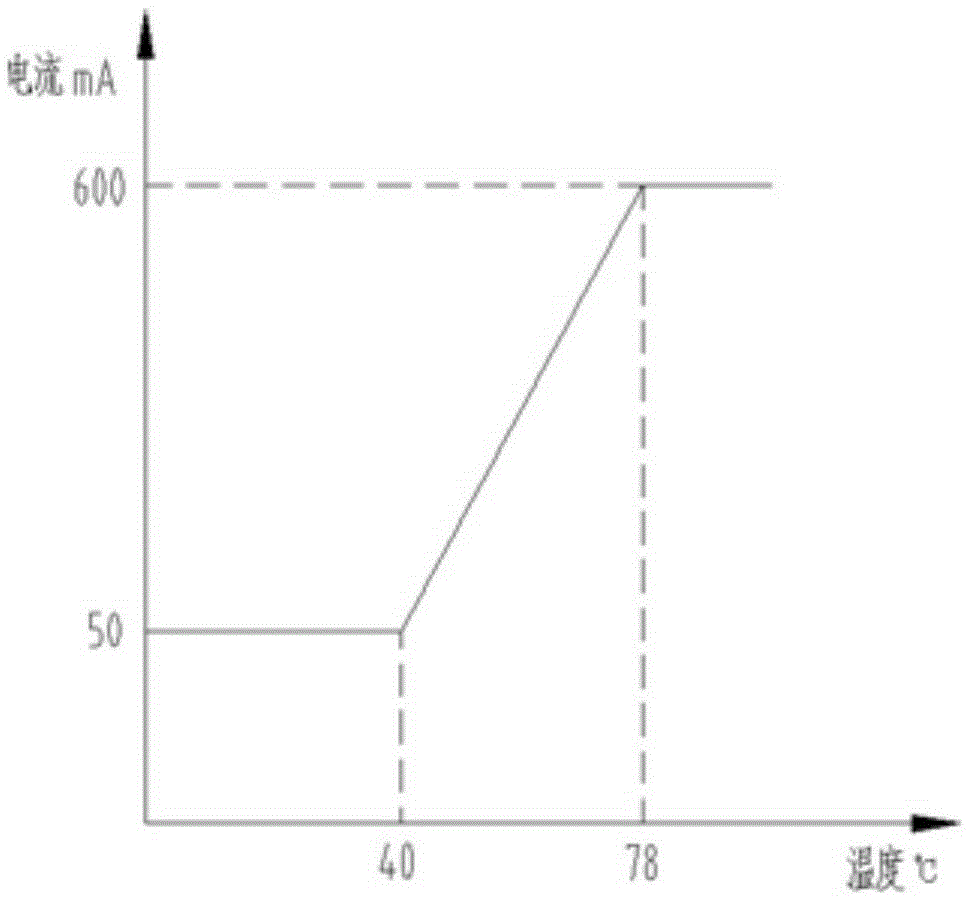
technical field [0001] The present invention relates to the technical field of heat dissipation control, in particular to a hydraulic independent heat dissipation control method, device and system. Background technique [0002] At present, in the control technology of the hydraulic oil temperature of the excavator, the existing technology is to adjust the current of the electromagnetic proportional pressure reducing valve of the cooling pump according to the change of the hydraulic oil temperature, so as to realize the output flow of the main pump and the speed of the cooling fan. adjustment, in this adjustment process, such as figure 1 As shown, the input current of the electromagnetic proportional pressure reducing valve is linearly proportional to the hydraulic oil temperature; when the hydraulic oil temperature t≤40°C, the input current of the electromagnetic proportional pressure reducing valve is a fixed value, and the output flow of the cooling pump is constant at thi...

Claims


Application Information

Patent Timeline
IPC IPC(8): F15B21/04
Inventor 秦勇张明珍梁恒姚小奇权龙侠
Owner ZOOMLION HEAVY IND CO LTD
Learn More