Eureka AIR delivers breakthrough ideas for toughest innovation challenges, trusted by R&D personnel around the world.

Machine and gate integrated gate

A one-type, machine door technology, applied in the field of lifting gates, can solve the problems of high cost of bottom pivoting flap doors, heavy civil engineering workload, difficult maintenance of rotating shafts, etc., and achieves convenient opening and closing of gates, less auxiliary buildings, and low maintenance convenient effect

Active Publication Date: 2016-02-10
THE JIANGSU GENERAL FACTORY OF WATER CONSERVANCY MACHINERY
View PDF5 Cites 1 Cited by
  • Summary
  • Abstract
  • Description
  • Claims
  • Application Information

AI Technical Summary

Problems solved by technology

The above-mentioned first four kinds of doors all need hoist buttresses, and the amount of civil work is large, while the lifting door also needs a working bridge and a hoist room, and the civil work is even greater. difficult maintenance

Method used


Image

  • Machine and gate integrated gate
  • Machine and gate integrated gate
  • Machine and gate integrated gate

Examples


Embodiment Construction

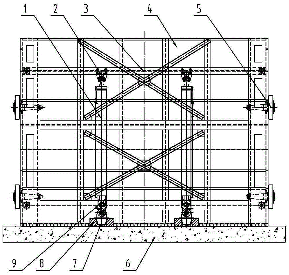
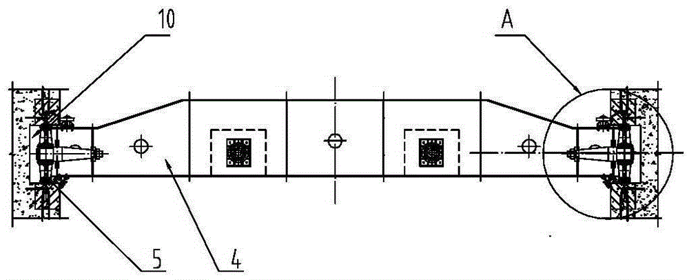
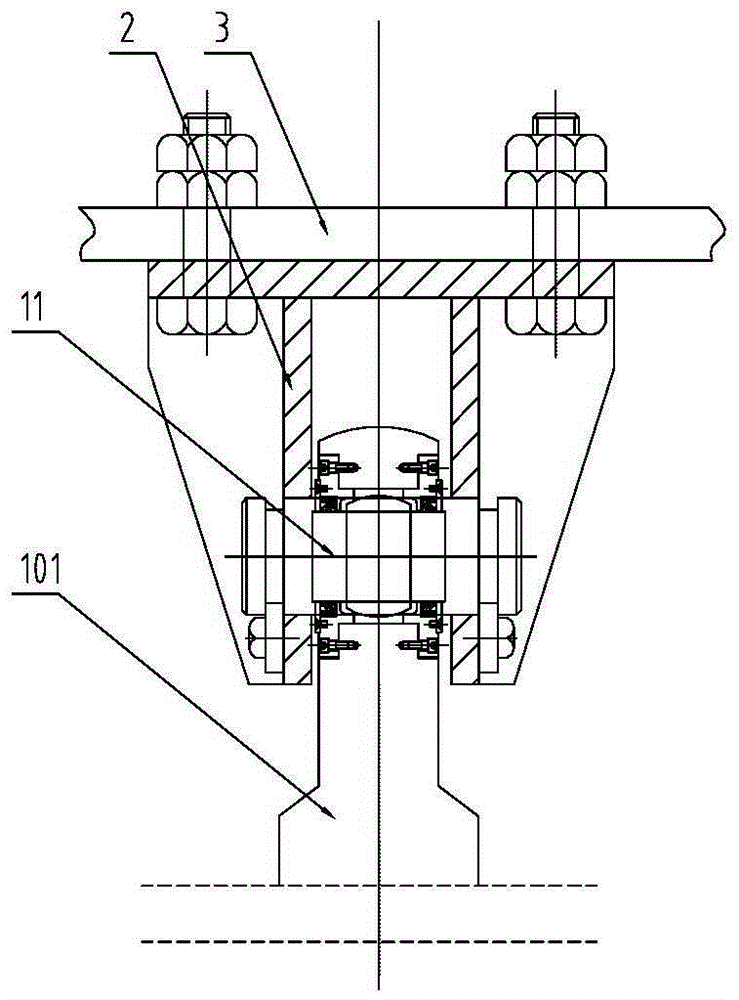
[0016] Such as Figure 1-5 As shown, it is a machine-door integrated gate, which includes a door body 4 blocked on the river, a bottom sill 6 is provided under the door body 4, door grooves 10 are provided on both sides of the door body 4, and a door groove 10 is provided on the backwater side of the door body 4. There is a crossbeam 3, and a hydraulic cylinder 1 is vertically arranged under the crossbeam 3, and two hydraulic cylinders 1 are arranged symmetrically on the backwater side of the door body 4. The piston rod 101 of the hydraulic cylinder 1 protrudes from the upper end of the hydraulic cylinder 1, and the hydraulic cylinder 1 The upper end of the piston rod 101 is connected with the fixed support 2 on the lower side of the beam 3 through the upper pin shaft 11, the lower end of the cylinder body 102 of the hydraulic cylinder 1 is connected with the movable support 9 through the lower pin shaft 12, and the lower end of the movable support 9 is provided with The taper...


PUM


Abstract

The invention discloses a machine and gate integrated gate in the field of gates. The gate comprises a gate body blocking a riverway, a bottom sill is arranged under the gate body, and gate grooves are formed in the two sides of the gate body. A cross beam is arranged on the landside of the gate body. Hydraulic oil cylinders are vertically arranged below the cross beam. Piston rods of the hydraulic oil cylinders extend out of the upper ends of the hydraulic oil cylinders. The upper end of the piston rod of each hydraulic oil cylinder is connected with a fixed support on the lower side of the cross beam through an upper pin shaft. The lower end of a cylinder body of each hydraulic oil cylinder is connected with a movable support through a lower pin shaft. A conical guide column is arranged at the lower end of each movable support. The bottom sill is provided with concave conical sleeves matched with the conical guide columns. The axis direction of the upper pin shafts is perpendicular to the water flow direction. The axis direction of the lower pin shafts is parallel to the water flow direction. The gate achieves machine and gate integration, and is stable in ascending and descending, convenient to open and close and convenient to maintain, and the number of auxiliary buildings is small.

Description

technical field [0001] The invention relates to a water conservancy facility, in particular to a lifting gate. Background technique [0002] With the expansion of city scale and the sudden increase of urban population, water consumption is increasing, and the uneven distribution of water resources in our country requires comprehensive dispatching and management; with the increase of comprehensive environmental management and water environment improvement, and urban construction In order to meet the needs of the landscape, various new gates have emerged as the times require, such as lying doors, flap doors, one-word doors, rising doors, bottom pivoted flap doors, etc. The above-mentioned first four kinds of doors all need hoist buttresses, and the amount of civil work is large, while the lifting door also needs a working bridge and a hoist room, and the civil work load is even greater. Difficult to maintain. Contents of the invention [0003] The object of the present inv...

Claims


Application Information

Patent Timeline
Patent Type & Authority Applications(China)
IPC IPC(8): E02B7/26E02B7/30E02B7/36
Inventor 张立明陆伟刚王勇徐磊张松
Owner THE JIANGSU GENERAL FACTORY OF WATER CONSERVANCY MACHINERY
Why Eureka
Eureka Blog
Learn More