
Turbine with hydraulic variable pitch system

A technology of hydraulic system and pitch control system, which is applied to propellers, engines, mechanical equipment, etc., and can solve problems such as large pitch control system, reduced turbine reliability, and reduced energy extraction efficiency

Inactive Publication Date: 2016-02-03
LOCKHEED MARTIN CORP
View PDF8 Cites 0 Cited by
  • Summary
  • Abstract
  • Description
  • Claims
  • Application Information

AI Technical Summary

Problems solved by technology

These pitch systems are large, heavy and complex, and they reduce the reliability of the turbine
Additionally, existing pitch systems require the blades to deviate from their ideal shape near the root, reducing energy extraction efficiency

Method used


Image

  • Turbine with hydraulic variable pitch system
  • Turbine with hydraulic variable pitch system
  • Turbine with hydraulic variable pitch system

Examples


Embodiment Construction

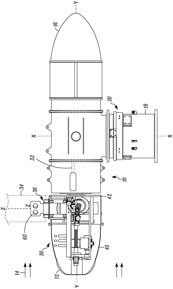
[0019] figure 1 The turbine 10 described herein is shown. The turbine 10 is designed to be positioned relative to a flowing fluid so as to be driven by the fluid. In one embodiment, the turbine 10 is submerged in water experiencing tidal flow. However, the turbine 10 may be submerged in any body of water (eg, river water) where there is a flow of water that may be used to generate electrical power. The concepts described herein may also be employed on wind driven turbines.

[0020] In use, the turbine 10 includes a front end 12 facing a flowing fluid indicated by arrow 14 and a rear end 16 . The turbine 10 is supported by a support structure 18 . Optionally, the yaw drive mechanism 20 may be arranged to rotate the turbine 10 about an axis X-X (which may be substantially vertical) to orient the turbine in a desired direction, generally facing the direction of fluid flow.

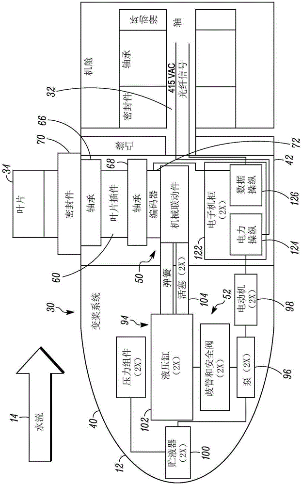
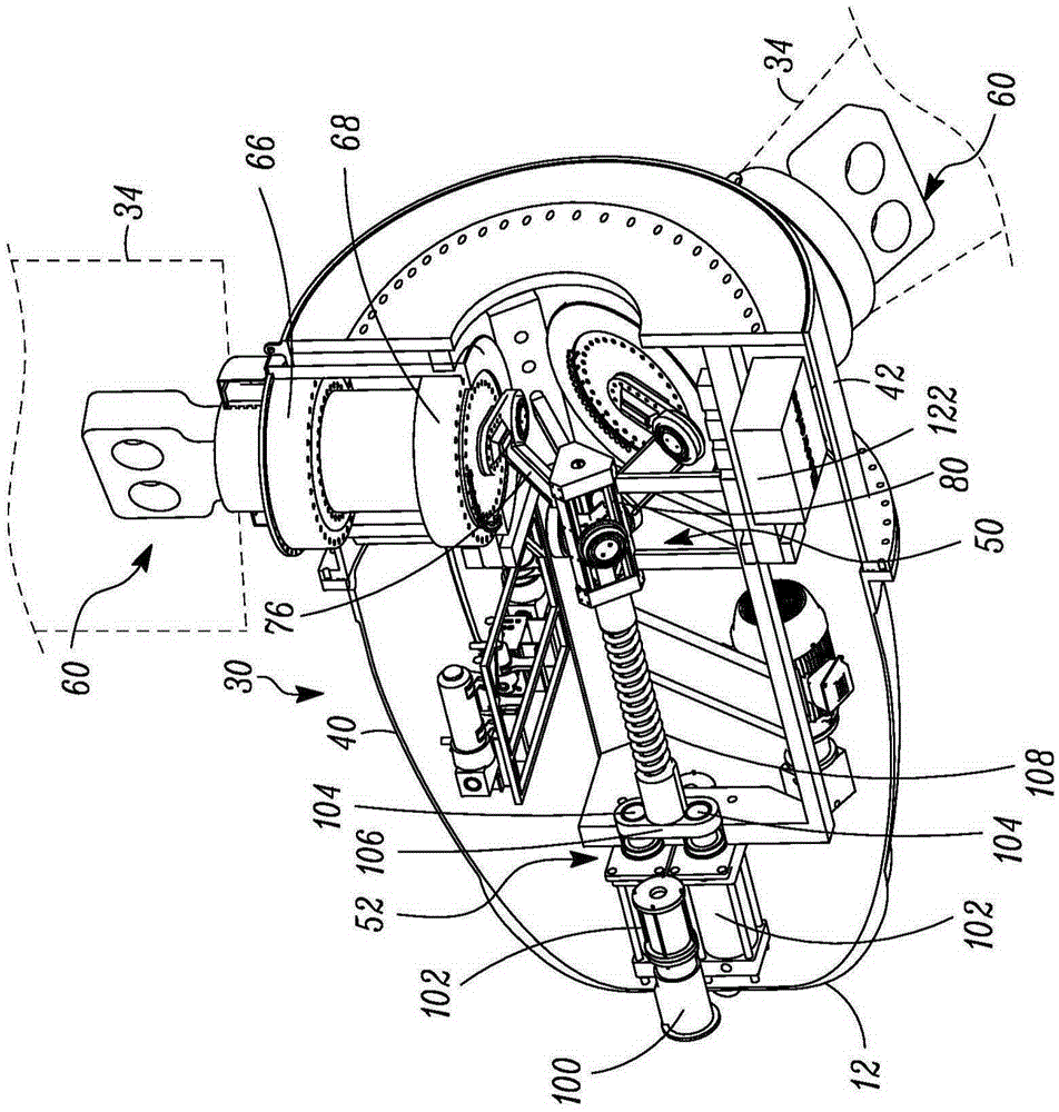
[0021] The turbine 10 includes a bladed rotor portion 30 rotatably arranged in front of the turbine s...


PUM


Abstract

A variable pitch system for a water or wind turbine includes a hydraulic system that includes a first hydraulic system (90) and a second, redundant hydraulic system (92) that are completely contained in a nose region of the turbine. The first and second hydraulic systems (90, 92) can each be used during operation on a predetermined operating schedule. In addition, each of the first and second hydraulic systems (90, 92) can also include a pressure relief valve to limit back pressure on the hydraulic system from dynamic loads on the turbine blades. The pitch of all the blades (34) are changed simultaneously using a common linear to rotary actuating mechanism. To aid in cooling, the hydraulic reservoirs (100) for the first and second hydraulic systems (90, 92) can be attached to the front wall of the nose housing (40), and fins (120) can be provided on the exterior of the nose housing (40) at the front end to enhance heat extraction.

Description

technical field [0001] The present technical disclosure relates to hydraulic or wind turbines, and in particular, to hydraulic or wind turbines with hydraulic pitch systems. Background technique [0002] Hydro or wind turbines extract energy from the flow of water or wind past the turbine. Examples of turbines include tidal turbines, river turbines, wind turbines, and the like. In the case of tidal turbines, the tidal flow is highly variable and is subject to extreme variations, swells and turbulence due to lunar spring / neap tide effects. [0003] Some hydro and wind turbine systems use fixed-pitch rotors to simplify their operation and increase overall turbine reliability. However, fixed-pitch rotors experience very large torques under high-speed flow conditions because the rotor has no load-shedding mechanism. They can be operated using a low RPM stall to absorb energy at very high torque or simply shut down during fast moving streams. [0004] Other hydro or wind turb...

Claims


Application Information

Patent Timeline
Patent Type & Authority Applications(China)
IPC IPC(8): F03D7/02B64C11/38B63H3/08F03B17/06F03B3/06
CPCB63H3/082F03B3/06F03B17/06F05B2260/74F05B2260/79B64C11/38F03D7/0224Y02E10/20F03D7/04Y02E10/72
Inventor R·P·克拉克M·F·海因茨I·M·莫拉扎尼B·厄本
Owner LOCKHEED MARTIN CORP
Learn More