
Digital television exciter capable of outputting multiple channels simultaneously

A simultaneous output, digital TV technology, applied in the direction of TV, color TV, color TV components, etc., can solve the problems of increased cost, the inability to have a large frequency interval for multiple channels, and the inability to achieve multi-channel broadcast, etc. Ease of use and simple structure

Inactive Publication Date: 2016-02-03
BEIJING BBEF SCI & TECH
View PDF8 Cites 0 Cited by
  • Summary
  • Abstract
  • Description
  • Claims
  • Application Information

AI Technical Summary

Problems solved by technology

[0002] Most of the existing digital TV exciters are single-channel exciters, which can only meet the transmission requirements of one channel. With the emergence of multi-channel and low-cost transmission requirements in remote areas, new requirements are put forward for the exciters.
There are many ways to implement multi-channel transmission: some use multiple digital TV exciters to synthesize, but the cost increases correspondingly; Perform digital-to-analog conversion and up-conversion processing. In this way, multiple channels share one analog channel, which can save the cost of system analog circuits. However, due to the limitation of device bandwidth, there cannot be a large frequency interval between multiple channels, which cannot be realized. Multi-channel broadcasting in the full frequency band of digital TV

Method used


Image

  • Digital television exciter capable of outputting multiple channels simultaneously
  • Digital television exciter capable of outputting multiple channels simultaneously

Examples


Embodiment

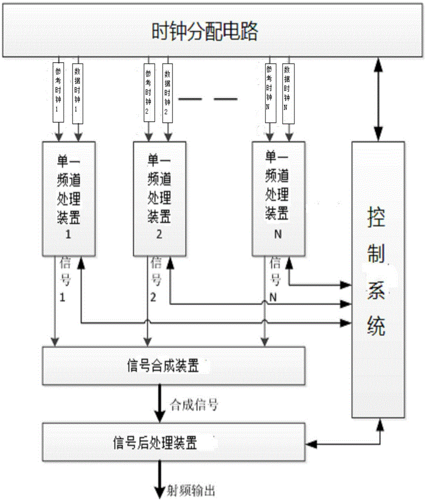
[0013] Such as figure 1 A digital TV exciter that outputs multiple channels at the same time is shown, including a clock distribution circuit. The clock distribution circuit is connected with N parallel clock circuits through a phase-locked loop, N≥2; the clock circuit includes reference clocks and data Clock, reference clock and data clock are arranged in parallel; each clock circuit is connected to a single channel processing device. The single channel processing device is connected with the signal synthesis device, and the signal synthesis device is connected with the signal post-processing device.

[0014] The clock distribution circuit, the single channel processing device and the signal post-processing device are all connected with the control system. In this way, the modulation mode, transmission code rate, working frequency, and power of each channel signal can be independently set and adjusted separately.

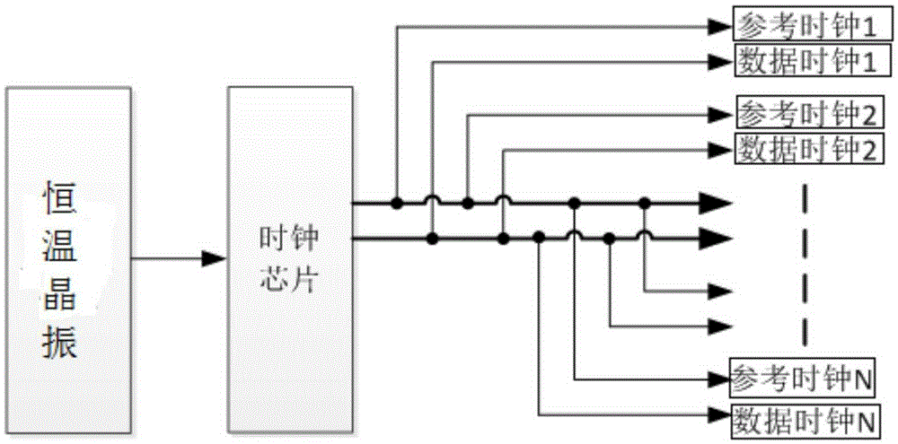
[0015] Such as figure 2 As shown, the clock distribution ...


PUM


Abstract

This invention discloses a digital television exciter capable of outputting multiple channels simultaneously. The digital television exciter comprises a clock distribution circuit; the clock distribution circuit is connected with N clock circuits arranged in parallel connection through phase-lock loops; N is not less than 2; the clock circuits comprise reference clocks and data clocks; the reference clocks and the data clocks are arranged in parallel connection; each clock circuit is connected with a single channel processing device; the single channel processing device is connected with a signal synthesizing device and a signal post-processing device in sequence; and the clock distribution circuit, the single channel processing device and the signal post-processing device are all connected with a control system. The digital television exciter has a simple structure and a convenient usage, reduces the hardware cost of the exciter, ensures that the work efficiency of each channel can be set freely in the whole television frequency band to break the limit of the signal bandwidth and realize a true multiple-channel exciter, meets the signal transmitting requirements of the multiple channels, and achieves the multiple-channel and low-cost application of the digital television in the remote areas.

Description

technical field [0001] The invention belongs to the field of electrical equipment, in particular to a digital TV exciter that simultaneously outputs multiple channels. Background technique [0002] Most of the existing digital TV exciters are single-channel exciters, which can only meet the transmission requirements of one channel. With the emergence of multi-channel and low-cost transmission requirements in remote areas, new requirements are also put forward for the exciters. There are many ways to implement multi-channel transmission: some use multiple digital TV exciters to synthesize, but the cost increases correspondingly; Perform digital-to-analog conversion and up-conversion processing. In this way, multiple channels share one analog channel, which can save the cost of system analog circuits. However, due to the limitation of device bandwidth, there cannot be a large frequency interval between multiple channels, which cannot be realized. Multi-channel broadcasting in...

Claims


Application Information

Patent Timeline
IPC IPC(8): H04N5/38
Inventor 龙平梁富林殷英张百川
Owner BEIJING BBEF SCI & TECH
Learn More