
Transformer oil clearance complex capacitance test method under low frequency sine excitation

A technology of sinusoidal excitation and transformer oil, which is applied in the direction of testing dielectric strength, instruments, measuring devices, etc., and can solve the problems affecting the application efficiency of the frequency domain dielectric response method.

Active Publication Date: 2016-02-03
SOUTHWEST JIAOTONG UNIV
View PDF3 Cites 4 Cited by
  • Summary
  • Abstract
  • Description
  • Claims
  • Application Information

AI Technical Summary

Problems solved by technology

The lower the frequency domain dielectric response test frequency is, the longer the test time is. Generally, it takes 40 minutes to scan from 1KHz frequency to 1mHz, and it takes 15 minutes to test only 1mHz frequency. For special working conditions, such as traction transformer maintenance time (open skylight ) is only about 2 hours, then the transformer maintenance time is not enough to complete the two links of transformer off-line cooling and frequency domain dielectric response test, which seriously affects the application efficiency of frequency domain dielectric response method in actual engineering, so it is urgently needed A method can accurately obtain the frequency domain spectrum of the complex capacitance of the transformer oil-paper insulation system, and can also improve the application efficiency of the frequency domain dielectric response method in practical engineering

Method used


Image

  • Transformer oil clearance complex capacitance test method under low frequency sine excitation
  • Transformer oil clearance complex capacitance test method under low frequency sine excitation
  • Transformer oil clearance complex capacitance test method under low frequency sine excitation

Examples


Embodiment Construction

[0048] The present invention will be further described below in conjunction with accompanying drawing:

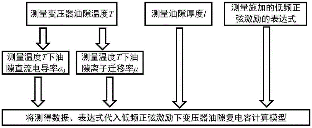
[0049] figure 1 Shown is a flow chart of a method for testing transformer oil gap complex capacitance under low-frequency sinusoidal excitation. It can be seen from the figure that a test method for transformer oil gap complex capacitance under low-frequency sinusoidal excitation mainly includes the following steps:

[0050] 1.1 Test to get the temperature T of the oil gap;

[0051] 1.2 Test to obtain the DC conductivity σ of the oil gap at T temperature 0 ;

[0052] 1.3 Test the ion mobility μ in the oil gap at T temperature;

[0053] 1.4 Test to obtain the thickness l of the oil gap;

[0054] 1.5 Test to obtain the amplitude U, phase ψ, and frequency f of the applied sinusoidal excitation, so as to obtain its instantaneous expression u(t);

[0055] 1.6 Substitute the data obtained in steps 1.1, 1.2, 1.3, 1.4, and 1.5 into the calculation model of oil gap complex cap...


PUM


Abstract

The present invention discloses a transformer oil clearance complex capacitance test method under a low frequency sine excitation. The method provided by the invention comprises: obtaining a direct current conductivity [Sigma]0, an ion mobility [Mu] and the thickness l of the oil clearance in the temperature T through a test, obtaining an amplitude U, a phase [Psi] and a frequency f applied by sine excitation through the test, and obtaining an instant expression u(t); then putting the obtained data (expression) in an oil clearance complex capacitance calculation model under the low frequency sine excitation; finally obtaining the complex capacitance of the oil clearance under the low frequency sine excitation. According to the method provided by the invention, obtained data (expression) through the test is putted into a calculation model to obtain the complex capacitance of the oil clearance through a numerical calculation method. On the basis of effectively obtaining the complex capacitance of the oil clearance, the method provided by the invention may solve the problem that the measurement time of the complex capacitance of the oil clearance under the low frequency sine excitation through adoption of an apparatus is long through the numerical calculation method, and the application efficiency of the frequency domain dielectric response method in the practical engineering may be improved.

Description

technical field [0001] The invention belongs to the field of transformer insulation state detection, and in particular relates to a method for testing transformer oil gap complex capacitance under low-frequency sinusoidal excitation. Background technique [0002] The oil-immersed transformer is the core equipment in the power system. The oil-paper insulation state is one of the important factors determining the insulation life of the oil-immersed transformer. The frequency domain dielectric response method is a recognized method that can effectively diagnose the moisture content of the oil-paper insulation and its aging state. one. The oil-paper insulation system of an oil-immersed transformer is composed of an oil gap, a paper tube pressure plate and a stay, etc. The oil gap is an important part of the oil-paper insulation system. When the oil-paper insulation system is tested for frequency-domain dielectric response, the external sinusoidal excitation voltage is scanned f...

Claims


Application Information

Patent Timeline
Patent Type & Authority Applications(China)
IPC IPC(8): G01R27/26G01R31/12
Inventor 王东阳周利军王路伽江俊飞刘伟迪黄军玲
Owner SOUTHWEST JIAOTONG UNIV
Learn More