
Small-diameter deep hole coaxiality detection method and device

A detection device and detection method technology, applied in the direction of measuring devices, optical devices, instruments, etc., can solve the problems of large processing errors, deep hole axis direction deviation, complex structure of detection devices, etc.

Inactive Publication Date: 2016-02-03
NAT ASTRONOMICAL OBSERVATORIES CHINESE ACAD OF SCI
View PDF7 Cites 8 Cited by
  • Summary
  • Abstract
  • Description
  • Claims
  • Application Information

AI Technical Summary

Problems solved by technology

[0006] When machining a small-diameter deep hole in the piston rod, due to the longer hole depth, the tool shake will become more and more obvious during the machining process, the axial direction of the deep hole will deviate, the diameter will also deviate, and the phenomenon of inclined hole and tapered hole will appear. If the error is large, it cannot meet the design requirements, so the coaxiality test must be carried out
There are also detection methods and devices for detecting the coaxiality of deep holes in the prior art, but the diameter range of the deep holes to be detected is relatively large, usually more than 50mm, and the structure of the detection device is relatively complicated, and it is not easy to realize miniaturization by reducing the size to adapt to small diameter deep holes. hole, and the detection device needs to be pulled to travel, it cannot be used for blind hole detection, it can only be used for through hole detection

Method used


Image

  • Small-diameter deep hole coaxiality detection method and device
  • Small-diameter deep hole coaxiality detection method and device
  • Small-diameter deep hole coaxiality detection method and device

Examples


Embodiment 1

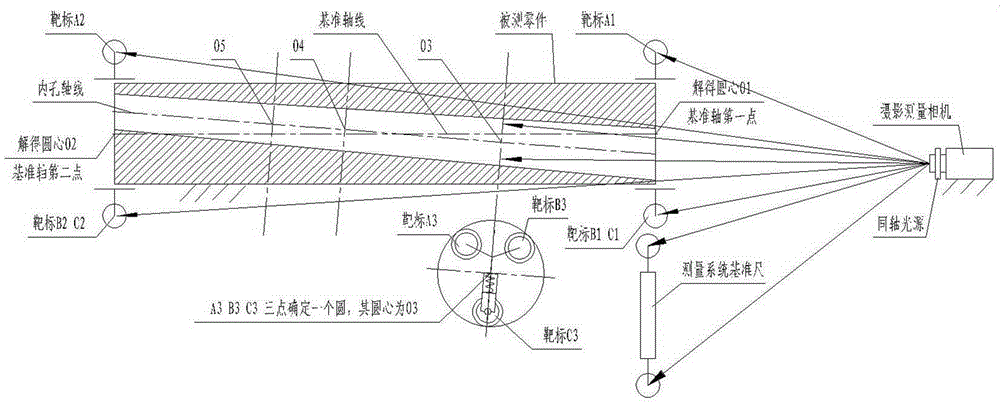
[0038] Such as image 3 , Figure 4 Shown is one of the embodiments of the detection method of the present invention. In this embodiment, a small-diameter deep hole coaxiality detection method is provided at one end of the deep hole. A number of targets are set on the device; the detection device is pushed to different depth positions in the deep hole to stop, and the target coordinate acquisition equipment collects the coordinate value of the target at the stop position of the detection device, and obtains the coordinate value of the center of the deep hole at this place by measuring. The coordinate value of the center of the stop position is measured to obtain the change value of the deep hole axis in the radial direction, and the change value of the deep hole diameter is obtained by measuring the target coordinate value of the stop position at different depths.

[0039] The detection device is provided with 3 legs, and each leg is provided with 1 target, and the 3 targets ...

Embodiment 2

[0059] Such as Figure 8 , Figure 9 Shown is Embodiment 2 of the present invention. In this embodiment, the contact head 2-1-1 is in the shape of an arc plate with rounded corners; the material of the leg 2-1 is tungsten steel.

[0060] Figure 8 The middle contact head 2-1-1 is still in a point contact state with the wall of the deep hole.

[0061] Figure 9 The middle contact head 2-1-1 is in line contact with the wall of the deep hole. Designed as a line contact state can improve the stability of the detection device in deep holes. In terms of detection accuracy, the point contact state is the best.


PUM


Abstract

The invention discloses a small-diameter deep hole coaxiality detection method. According to the method, one end of a deep hole is provided with target coordinate acquisition equipment, the deep hole is provided with a detection device, the detection device is provided with multiple targets, the detection device is pushed to different depths in the deep hole to stop, coordinate values of the targets at the stop positions of the detection device are acquired by the target coordinate acquisition equipment, a center of circle coordinate value of the deep hole is measured, through center of circle coordinate values of different depth stop positions at the deep hole, a change value of an axial line of the deep hole in a radial direction is measured, a deep hole diameter change value is measured through the target coordinate values at the different depth stop positions. A shooting measurement camera is employed by the target coordinate acquisition equipment, faces of the targets detected by the shooting measurement camera are arranged on one plane, namely the target plane, after the detection device stops at the different depth positions in the deep hole, the target plane and the axial line of the deep hole are automatically perpendicularly to each other.

Description

technical field [0001] The invention relates to a method for detecting the coaxiality of a small-diameter deep hole, in particular to a method for measuring the center of a circle at different positions in the small-diameter deep hole and a method for measuring the diameter. The invention also relates to a small-diameter deep hole coaxiality detection device. Background technique [0002] The 500m aperture spherical radio telescope FAST (Five-hundred-meter Aperture SphericalradioTelescope) will be the largest and most sensitive radio astronomy telescope in the world. Using the karst depression in Guizhou as the station site, a spherical crown reflector is laid in the depression, and a parabola is formed through active control to converge electromagnetic waves. A light steel cable is used to drag the feed platform to realize the pointing and tracking of the telescope. [0003] The reference surface of the FAST active reflector is a spherical surface with a diameter of 500m a...

Claims


Application Information

Patent Timeline
Patent Type & Authority Applications(China)
IPC IPC(8): G01B11/27
Inventor 薛建兴王启明吴明长高原
Owner NAT ASTRONOMICAL OBSERVATORIES CHINESE ACAD OF SCI
Learn More