A cable hole blocker
A plugging device and hole technology, applied in the direction of pipes, pipes/pipe joints/fittings, mechanical equipment, etc., can solve the problems of difficult disassembly, low construction efficiency, damage, etc., and achieve good practical performance, high construction efficiency, and easy installation The effect of disassembly
- Summary
- Abstract
- Description
- Claims
- Application Information
AI Technical Summary
Problems solved by technology
Method used
Image


Examples
Embodiment 1
[0041] Embodiment 1: One-piece cable hole plugging device
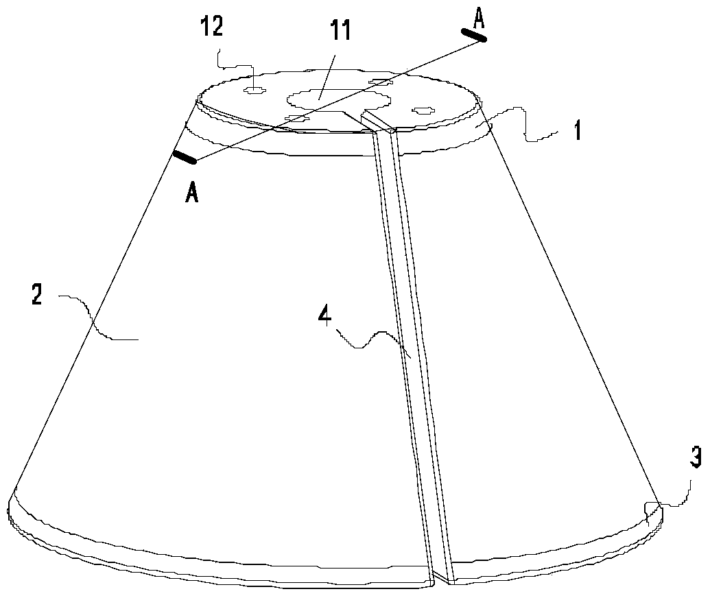
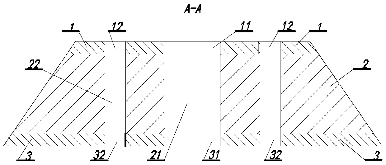
[0042] Such as Figure 1-Figure 2 As shown, the preferred embodiment 1 of the present invention discloses an integrally formed cable hole blocker, which includes a first hard layer 1, a soft rubber layer 2 and a second hard layer 3, the soft rubber layer and the two The hard layer is integrally formed by insert molding process. The hard layer is made of PS material, and the soft layer is made of PE material.
[0043] The first hard layer 1, the soft rubber layer 2 and the second hard layer 3 are respectively provided with a cable hole 11, a cable hole 21 and a cable hole 31 whose axes coincide; 4 threaded holes 12, 4 light holes 22 are evenly distributed around the cable hole 21, 4 light holes 32 are evenly distributed around the cable hole 31; the axes of the threaded holes 12, the light holes 22 and the light holes 32 coincide; The cable hole 11, the cable hole 21 and the cable hole 31 form the cable hole of the ...
Embodiment 2
[0047] Example 2: Cable Hole Closure Device with Split Structure
[0048] Figure 4 It is a schematic cross-sectional view of the split occluder involved in the preferred embodiment 2 of the present invention, and the cut position is as follows: figure 1 shown. read Figure 4 It can be seen that the occluder disclosed in Example 2 includes a first hard layer 10, a soft rubber layer 20, and a second hard layer 30; the soft rubber layer and the two hard layers are a separate structure.
[0049] read Figure 4 It can be seen that the central positions of the first hard layer 10, the soft rubber layer 20 and the second hard layer 30 are respectively provided with a cable hole 101, a cable hole 201 and a cable hole 301, and the axes of the three cable holes coincide. Form the cable hole of the cable hole blocker in this embodiment. Four threaded holes 102 are arranged on the first hard layer 10, and the four threaded holes 102 are evenly distributed around the axis of the firs...
Embodiment 3
[0055] Embodiment 3: The soft rubber layer is a cable hole plugging device with a fan-shaped sheet structure
[0056] The basic components, connections, functions and principles of the components in Embodiment 3 of the present invention are exactly the same as in Embodiment 2, the difference is that the soft glue layer 20' in Embodiment 3 is Figure 6 The fan sheet structure shown in , when the fan sheet structure is enclosed, can form the conical structure in embodiment 2, and an opening is formed at the overlapping seam; the soft rubber layer and the two hard layers 10' and 30' The connection and fixing relationship between them is the same as the various structures and cooperation relationships disclosed in Embodiment 2, and will not be repeated here. The soft rubber layer is processed into a fan-shaped sheet structure, which is convenient for storage, packaging and transportation. In addition, as an improvement, snap joints can also be provided at overlapping joints of th...
PUM
 Abstract
Description
Claims
Application Information
 - R&D
- Intellectual Property
- Life Sciences
- Materials
- Tech Scout
- Unparalleled Data Quality
- Higher Quality Content
- 60% Fewer Hallucinations
Browse by: Latest US Patents, China's latest patents, Technical Efficacy Thesaurus, Application Domain, Technology Topic, Popular Technical Reports.
© 2025 PatSnap. All rights reserved.Legal|Privacy policy|Modern Slavery Act Transparency Statement|Sitemap|About US| Contact US: help@patsnap.com