
Variable capacity hydraulic device

A hydraulic device and capacity technology, applied in the direction of liquid variable displacement machinery, multi-cylinder pumps, machines/engines, etc., can solve the problems of decreased volumetric efficiency of hydraulic pumps, high pressure, increased driving noise of hydraulic pumps, etc.

Active Publication Date: 2016-02-03
NABLESCO CORP
View PDF6 Cites 5 Cited by
  • Summary
  • Abstract
  • Description
  • Claims
  • Application Information

AI Technical Summary

Problems solved by technology

[0007] On the other hand, since the pressure of the hydraulic oil applied to the oil sump is constant (self pressure), when the working piston moves in the direction to separate from the swash plate, the pressure applied to the oil sump becomes excessive
In such a case, the swash plate may float up from the casing, and the leakage of the hydraulic oil supplied to the oil tank may increase, resulting in a decrease in the volumetric efficiency of the hydraulic pump.
In addition, since the swash plate floats up from the casing, it may cause micro-vibration of the swash plate and increase the driving noise of the hydraulic pump

Method used


Image

  • Variable capacity hydraulic device
  • Variable capacity hydraulic device
  • Variable capacity hydraulic device

Examples


Embodiment Construction

[0023] Hereinafter, a variable displacement hydraulic device according to an embodiment will be described with reference to the drawings.

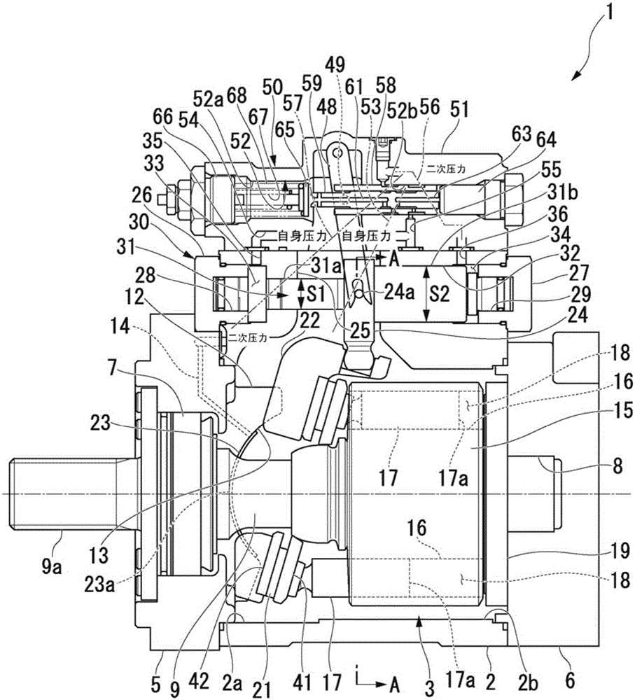
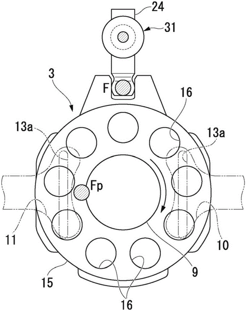
[0024] figure 1 is a sectional view of the hydraulic pump, figure 2 is along figure 1 A cross-sectional view of the A-A line.

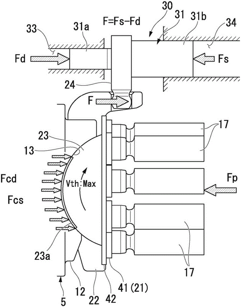
[0025] Such as figure 1 As shown, the hydraulic pump 1 is a so-called swash plate variable capacity hydraulic pump, comprising: a casing 2, which is cylindrical; a rotating mechanism 3, which is rotatably arranged in the casing 2; a swash plate 22, It is installed in the casing 2 to determine the discharge flow rate of hydraulic oil; the working piston mechanism 30 controls the inclination angle (Vth) of the swash plate 22; and the servo mechanism 50 is installed on the outer peripheral surface of the casing 2 to drive the The working piston mechanism 30 supplies predetermined hydraulic oil to the working piston mechanism 30 . In addition, in the following description, the direction of the rotation axis o...


PUM


Abstract

The invention provides a variable capacity hydraulic device. The variable capacity hydraulic device includes a housing, a cylinder, pistons, an inclined plate, an oil groove, a work piston and a servo mechanism, wherein the cylinder is arranged in the housing in the rotary way; the pistons are respectively inserted in a plurality of cylinder holes in the cylinder; the inclined plate is arranged on the pistons and on the opposite side end in the cylinder holes of the pistons, and is arranged in the sliding way relative to the opposite side end, and can move in the inclined way and can slide on the housing; the oil groove is formed on any one of the sliding surface of the housing and the sliding surface of the inclined plate, and is used for guaranteeing the sliding property between the housing and the inclined plate; the work piston is used for moving the inclined plate in the inclined way; and the servo mechanism supplies hydraulic oil to drive the work piston and supplies the secondary pressure generated by the servo mechanism to the oil groove.

Description

technical field [0001] The invention relates to a variable capacity hydraulic device. Background technique [0002] As a variable displacement hydraulic system, there is a swash plate type variable displacement hydraulic pump (hereinafter simply referred to as a hydraulic pump) for supplying hydraulic oil to various hydraulic actuators mounted on construction equipment such as a hydraulic excavator. Such a hydraulic pump has a rotating shaft rotatably supported in a casing, and the cylinder is rotated integrally with the rotating shaft. The cylinder body is provided with a plurality of cylinder holes, and a piston is inserted into each cylinder hole. Furthermore, the cylinder chamber is constituted by the cylinder bore and the piston. [0003] In addition, a swash plate is provided at the end of the piston opposite to the end where the cylinder chamber is formed so that the swash plate can tilt and move relative to the housing, and the piston slides along the swash plate. ...

Claims


Application Information

Patent Timeline
Patent Type & Authority Applications(China)
IPC IPC(8): F04B1/22
Inventor 斋藤宪夫
Owner NABLESCO CORP
Learn More