
Linear evaporation source and evaporation plating device

An evaporation source and linear technology, applied in the field of linear evaporation source and evaporation equipment, can solve the problems of lower evaporation efficiency, uneven temperature, and clogged nozzles of evaporation materials, so as to improve evaporation efficiency, uniform temperature, and avoid overheating different or less effective

Active Publication Date: 2016-02-03
合肥欣奕华智能机器股份有限公司
View PDF5 Cites 32 Cited by
  • Summary
  • Abstract
  • Description
  • Claims
  • Application Information

AI Technical Summary

Problems solved by technology

[0006] However, in the case of using a linear evaporation source, since the heat of the evaporation source is radiated to the nozzle part, the temperature is not uniform, and the evaporation material may clog the nozzle, reducing the evaporation efficiency.

Method used


Image

  • Linear evaporation source and evaporation plating device
  • Linear evaporation source and evaporation plating device
  • Linear evaporation source and evaporation plating device

Examples


Embodiment Construction

[0043] The following will clearly and completely describe the technical solutions in the embodiments of the present invention with reference to the accompanying drawings in the embodiments of the present invention. Obviously, the described embodiments are only some, not all, embodiments of the present invention. Based on the embodiments of the present invention, all other embodiments obtained by persons of ordinary skill in the art without making creative efforts belong to the scope of patent protection of the present invention.

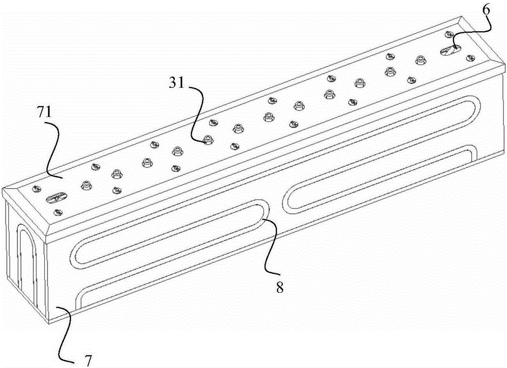
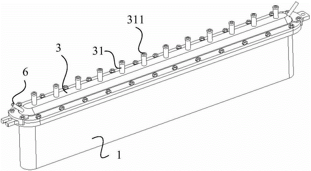
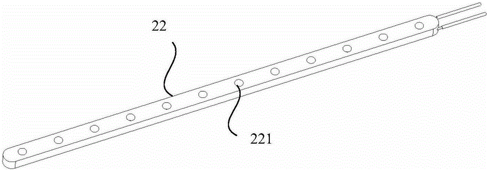
[0044] Such as figure 1 and figure 2 shown, where: figure 1 A schematic diagram of the structure of the linear evaporation source provided by the embodiment of the present invention; figure 2 Another schematic diagram of the structure of the linear evaporation source provided by the embodiment of the present invention; the linear evaporation source provided by the present invention includes: a crucible 1 with an open end, and a hollow chamber for...


PUM


Abstract

The invention discloses a linear evaporation source and an evaporation plating device in order to reduce the phenomenon that nozzles are blocked and improve the evaporation plating efficiency. The linear evaporation source comprises a crucible with one end open, a first heater and a top cover, wherein a hollow cavity used for containing evaporation plating materials is arranged in the crucible, the first heater surrounds the outer side of the crucible and provides heat for the crucible, the open end of the crucible is covered with the top cover, and the top cover is provided with a plurality of nozzles used for jetting gasified evaporation plating materials to a substrate to be plated. The linear evaporation source further comprises a second heater providing the same heat for each nozzle, and the second heater comprises heating ends corresponding to the nozzles one to one and wrapping the outer surfaces of the corresponding nozzles.

Description

technical field [0001] The invention relates to the technical field of evaporation equipment, in particular to a linear evaporation source and evaporation equipment. Background technique [0002] In recent years, organic electroluminescence display (OLED), as a new type of flat panel display, has gradually received more attention. Due to its active light emission, high luminous brightness, high resolution, wide viewing angle, fast response speed, low energy consumption, and flexibility, it has become a next-generation display technology that may replace liquid crystal display. [0003] Evaporation devices are experimental and production equipment used in the field of thin film preparation, and are widely used in organic optoelectronic fields such as organic light-emitting diodes (OLEDs), organic solar cells (OPVs), and organic field-effect transistors (OFETs). [0004] An organic light-emitting diode (Organic Light-Emitting Diode, referred to as OLED) manufactures a carrier...

Claims


Application Information

Patent Timeline
IPC IPC(8): C23C14/24
Inventor 金薰李浩永卢正权金甲锡
Owner 合肥欣奕华智能机器股份有限公司
Learn More