Core tube inverse superimposed underground diaphragm wall and construction method thereof

A technology of underground diaphragm wall and construction method, which can be applied to artificial islands, sheet pile walls, water conservancy projects, etc., and can solve the problems of not being able to meet the needs of the ground connection wall of the core tube, effectively resisting shear force, and destroying the integrity of the wall. , to achieve the effect of improving construction quality, reducing construction difficulty and ensuring construction efficiency

Active Publication Date: 2016-01-27
CHINA ARCHITECTURE DESIGN & RES GRP CO LTD
View PDF6 Cites 5 Cited by
  • Summary
  • Abstract
  • Description
  • Claims
  • Application Information

AI Technical Summary

Problems solved by technology

However, the existing ground-to-wall joints have not formed good continuity and cannot effectively resist shear force
At the same time, due to the gaps between the sections, an additional staggered shear force between the sections caused by the vertical load will be generated, which will damage the integrity of the wall
[0004] It can be seen that the above-mentioned existing underground diaphragm wall sub-section connection form cannot meet the needs of the core tube ground connection wall, and needs to be further improved.

Method used


Image

  • Core tube inverse superimposed underground diaphragm wall and construction method thereof
  • Core tube inverse superimposed underground diaphragm wall and construction method thereof
  • Core tube inverse superimposed underground diaphragm wall and construction method thereof

Examples


Embodiment Construction

[0036] The invention relates to a core tube inverse superimposed underground continuous wall, which includes a core tube underground continuous wall below the elevation of the raft top and a core tube underground continuous wall above the raft top elevation.

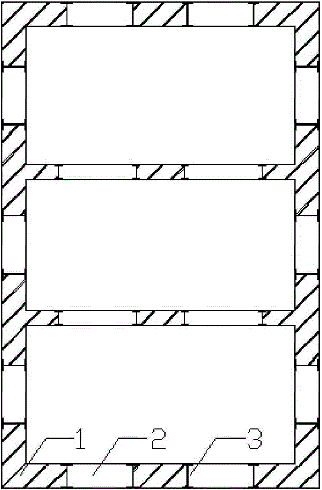
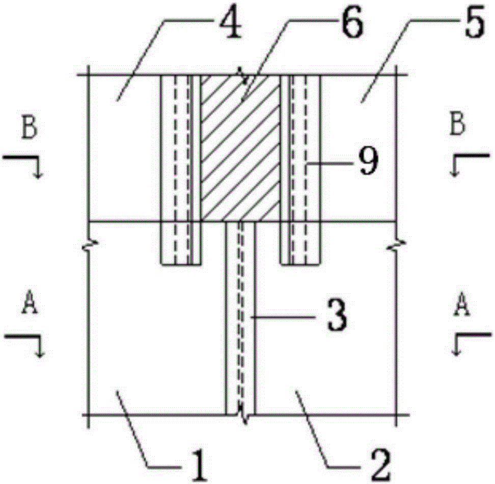
[0037] Refer to the attached figure 1 , 3 It can be seen from and 4 that the underground diaphragm wall of the core tube below the elevation of the top of the raft includes a first leading section 1 and a first subsequent section 2, and the first leading section 1 and the first subsequent section 2 are rigidly connected, Such as the use of I-shaped steel 3 connection.

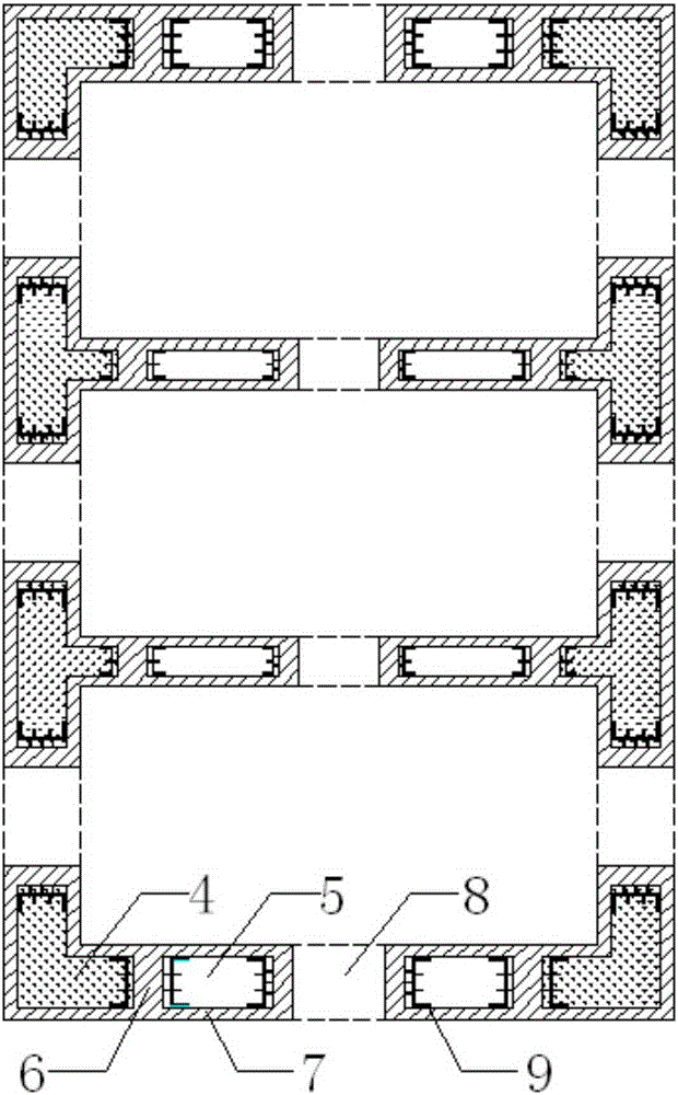
[0038] Refer to the attached figure 2 , 3 It can be seen from and 5 that the underground diaphragm wall of the core tube above the elevation of the top of the raft includes the second leading section 4, the second subsequent section 5, the connecting beam 8, the space between the second leading section 4 and the second subsequent section 5 and The po...


PUM


Abstract

The invention discloses a core tube inverse superimposed underground diaphragm wall. The core tube inverse superimposed underground diaphragm wall comprises a core tube underground diaphragm wall body below a raft top elevation and a core tube underground diaphragm wall body above the raft top elevation. The underground diaphragm wall body below the raft top elevation comprises first advance width sections and first follow-up width sections. The underground diaphragm wall body above the raft top elevation comprises second advance width sections, second follow-up width sections, connecting beams, post-pouring gap sections arranged at the connecting positions of the second advance width sections and the second follow-up width sections and the connecting positions of the width sections and the connecting beams, and outer lining walls arranged at the outer sides of the width sections and the post-pouring gap sections. Wall body lacing wires and stirrups are pre-embedded in the two side edges of steel reinforcement cages of the second advance width sections and the second follow-up width sections respectively. Box irons are pre-embedded in the end portions of the two sides of the second advance width sections and the second follow-up width sections, and the box irons stretch into the underground diaphragm wall body below the raft top elevation. The invention further discloses a construction method for the core tube inverse superimposed underground diaphragm wall. According to the core tube inverse superimposed underground diaphragm wall, the outer lining walls are arranged additionally on the two sides of the underground diaphragm wall body above the raft top elevation, and the problem that an existing underground diaphragm wall is insufficient in carrying capacity is solved; in addition, two different underground diaphragm wall connecting modes are adopted, so that not only are requirements for stressing and constructing met, but also the shear performance of the underground diaphragm wall is guaranteed.

Description

technical field [0001] The invention relates to the technical field of structural engineering, in particular to a core tube reverse-action superimposed underground continuous wall and a construction method thereof. Background technique [0002] The reverse method means that the basement structure is constructed layer by layer from top to bottom. First, the earthwork above the working face of the first underground floor is excavated and constructed. After the construction of the first basement structure is completed, the earthwork of the second underground layer is excavated. Layer down construction until the base plate is poured. At the same time, the superstructure is continuously constructed, so the reverse method can make the construction of the superstructure of the building and the construction of the underground foundation parallel three-dimensional operation, save the construction period, and maximize the use of the underground space. It is an effective method for the...

Claims


Application Information

Patent Timeline
Patent Type & Authority Applications(China)
IPC IPC(8): E02D29/045E02D5/18
Inventor 范重刘云博胡纯炀赵长军
Owner CHINA ARCHITECTURE DESIGN & RES GRP CO LTD
Why Eureka
Try Eureka