Workpiece circulation type automatic sand returning dry sand blasting room

A circulating, dry sandblasting technology, applied in the direction of manufacturing tools, metal processing equipment, abrasive jet machine tools, etc., can solve the problems of affecting the quality of spraying, stacking together, and low work efficiency, so as to achieve circulation and continuity, and improve Sandblasting efficiency, reasonable structure effect

Inactive Publication Date: 2016-01-27
重庆明治百通机械制造股份有限公司
View PDF15 Cites 9 Cited by
  • Summary
  • Abstract
  • Description
  • Claims
  • Application Information

AI Technical Summary

Problems solved by technology

[0002] Sand blasting technology is a commonly used technology for surface treatment in the manufacturing industry. In order to realize the spraying of the workpiece, the surface of the workpiece must have a certain adhesion surface, that is, the surface of the workpiece must have a certain roughness, so that the paint layer, etc. The material for surface treatment is attached to the surface of the workpiece to realize the beautification and treatment of the surface of the workpiece; while the current sandblasting is mainly to take the workpiece to the place, the operator sprays, and then carries the workpiece out, and then carries out the subsequent spraying work In this way, the work efficiency is extremely low, and the workpieces are piled up during sandblasting, and the surface roughness of the workpiece after sandblasting is inconsistent, which affects the quality of subsequent spraying; at the same time, the sand produced in the sandblasting process needs to be recycled manually. treatment, the timely recovery and utilization of sand materials cannot be realized

Method used


Image

  • Workpiece circulation type automatic sand returning dry sand blasting room
  • Workpiece circulation type automatic sand returning dry sand blasting room

Examples


Embodiment Construction

[0014] All features disclosed in this specification, or steps in all methods or processes disclosed, may be combined in any manner, except for mutually exclusive features and / or steps.

[0015] Any feature disclosed in this specification (including any appended claims, abstract and drawings), unless expressly stated otherwise, may be replaced by alternative features which are equivalent or serve a similar purpose. That is, unless expressly stated otherwise, each feature is one example only of a series of equivalent or similar features.

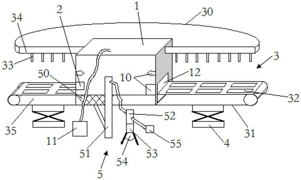
[0016] Such as Figure 1 to Figure 2 As shown, the preferred embodiment of the dry sand blasting room of the present invention includes a sand blasting room body 1, a control system 2, a workpiece circulation feeding system 3, an automatic sand returning system 5, a sand blasting system 10 and a dust removal system. System 11; control system 2 is used to control the opening and closing of sandblasting system 10, dust removal system 11 and wor...


PUM


Abstract

The invention discloses a workpiece circulation type automatic sand returning dry sand blasting room. The workpiece circulation type automatic sand returning dry sand blasting room comprises a sand blasting room body, circular workpiece supply systems, a control system, an automatic sand returning system, a sand blasting system and a sand removing system. The circular workpiece supply systems are divided into the upper circular workpiece supply system and the lower circular workpiece supply system. Lifting mechanisms are arranged below the lower circular workpiece supply system. A plurality of workpiece fixing bases are arranged on the lower circular workpiece supply system. A plurality of workpiece hooks are arranged on the upper circular workpiece supply system. Lifting doors are arranged on the two side faces of the sand blasting room body. The automatic sand returning system is composed of a sand falling groove, a lifting machine, a separating machine, a sand returning box, a pressure tank and a waste basket. According to the workpiece circulation type automatic sand returning dry sand blasting room, circular workpiece supply is achieved through the circular workpiece supply systems, and the sand blasting efficiency is improved. By means of the automatic sand returning system, sand materials are recycled, separated and repeatedly utilized, indoor accumulated sand is removed in time, sand material accumulation is prevented, and therefore the sand blasting effect cannot be affected.

Description

technical field [0001] The invention belongs to the technical field of surface treatment, and in particular relates to a dry sandblasting room with automatic sand return and circulation for workpieces. Background technique [0002] Sand blasting technology is a commonly used technology for surface treatment in the manufacturing industry. In order to realize the spraying of the workpiece, the surface of the workpiece must have a certain adhesion surface, that is, the surface of the workpiece must have a certain roughness, so that the paint layer, etc. The material for surface treatment is attached to the surface of the workpiece to realize the beautification and treatment of the surface of the workpiece; while the current sandblasting is mainly to take the workpiece to the place, the operator sprays, and then carries the workpiece out, and then carries out the subsequent spraying work In this way, the work efficiency is extremely low, and the workpieces are piled up during sa...

Claims


Application Information

Patent Timeline
IPC IPC(8): B24C3/12B24C3/02B24C9/00
Inventor 刘绍明
Owner 重庆明治百通机械制造股份有限公司
Why Eureka
Try Eureka