A method for manufacturing a combination mold for forming a floor heating pipe groove

A technology of combining molds and floor heating pipes, used in forming tools, manufacturing tools, metal processing equipment, etc., can solve the problems of easy occurrence of wrinkles and difficulty in ensuring the consistency of the size of the floor heating pipe grooves, so as to reduce internal stress and ensure dimensional consistency. , the effect of large molding freedom

Active Publication Date: 2017-04-26
ANHUI LINGFENG METALLURGICAL MACHINERY
View PDF6 Cites 0 Cited by
  • Summary
  • Abstract
  • Description
  • Claims
  • Application Information

AI Technical Summary

Problems solved by technology

[0008] The invention provides a floor heating pipe groove forming method to solve the problems in the prior art that the floor heating pipe groove cannot be accurately processed at one time, the floor heating pipe groove is prone to wrinkles after processing, and the size consistency of the floor heating pipe groove in the length direction is difficult to ensure. The manufacturing method of the combined mold, the mold manufactured by the invention realizes the function of processing the floor heating pipe groove accurately and without wrinkles at one time, and ensures the dimensional consistency of the floor heating pipe groove in the length direction

Method used


Image

  • A method for manufacturing a combination mold for forming a floor heating pipe groove
  • A method for manufacturing a combination mold for forming a floor heating pipe groove
  • A method for manufacturing a combination mold for forming a floor heating pipe groove

Examples


Embodiment 1

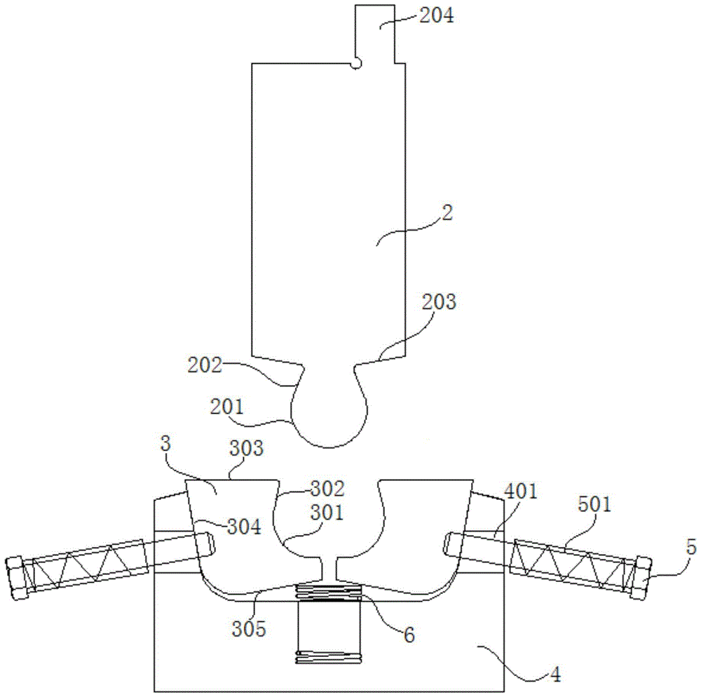
[0048] refer to figure 1 , figure 2 and image 3 , the combined mold for forming the floor heating pipe groove of the present embodiment includes an upper mold 2, a forming block 3, a lower mold base 4, a bolt 5 and a compression spring 501, and a U-shaped groove is opened on the lower mold base 4, and the left and right sides of the U-shaped groove Two molding blocks 3 are symmetrically arranged; side through holes 401 are symmetrically arranged on both sides of the lower mold base 4, and the bolts 5 pass through the side through holes 401 to be threadedly connected with the molding blocks 3, and the compression spring 501 is sleeved on the bolts 5, The diameter of compression spring 501 is greater than the inner diameter of side through hole 401, and one end of compression spring 501 is against the head of bolt 5, and the other end of compression spring 501 is against the outside of side through hole 401, and compression spring 501 ends and bolt 5. There is a rubber ring ...

Embodiment 2

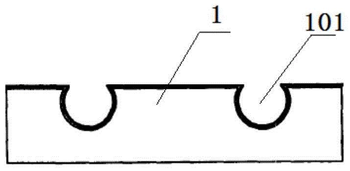
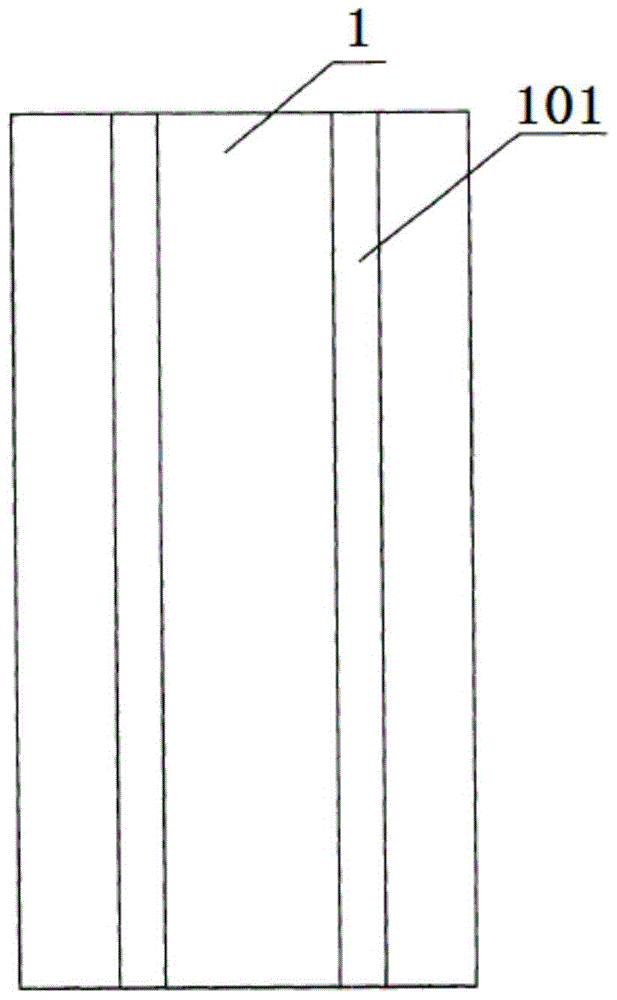
[0055] refer to figure 1 , figure 2 and image 3, a floor heating pipe groove forming method using the floor heating pipe groove forming combination mold of embodiment 1, comprising the following steps: 1), installing the mold: installing and fixing the upper mold 2 on the upper tool rest of the bending machine, and placing the lower The mold base 4 is installed and fixed on the lower tool rest of the bending machine, so that the upper mold 2 is directly facing the lower mold base 4 below, that is, the protrusion is located in the middle between the two arc-shaped depressions on the two forming blocks 3 Above; 2), feeding: place the heat conducting layer 1 blank on the top surface 303 of the two molding blocks 3, adjust the position of the heat conducting layer 1 blank, so that the part of the heat conducting layer 1 blank that needs to be stamped out of the floor heating pipe groove 101 is located at the two 3), stamping: the upper die 2 presses down with the upper knife r...

Embodiment 3

[0057] refer to figure 1 , figure 2 and image 3 , The manufacturing method of the floor heating pipe groove forming combination mold of the present embodiment includes the following steps: step (1), blanking; step (2), forging; step (3), rough machining; step (4), punching; Step (5), heat treatment, the heat treatment process in step (5) is quenching and tempering treatment, the hardness of mold after quenching and tempering treatment is HRC40~45, and the hardness of mold after quenching and tempering treatment in the specific present embodiment is HRC40; Step (6 ),finishing.

[0058] Wherein, the structure of the combined mold for forming the floor heating pipe groove is as follows: the combined mold for forming the floor heating pipe groove includes an upper mold 2, a forming block 3, a lower mold base 4, a bolt 5 and a compression spring 501, and the lower mold base 4 is provided with a U-shaped groove, Two molding blocks 3 are symmetrically arranged in the U-shaped gr...


PUM


Abstract

The invention discloses a method for manufacturing a floor heating pipeline groove forming combination die, and relates to the field of forming combination dies special for floor heating pipeline grooves. The method comprises the following steps of (1) blanking, (2) forging, (3) rough machining, (4) punching, (5) thermal treatment and (6) finish machining. According to the structure of the die, a U-shaped groove is formed in a lower die holder, and two forming blocks are arranged in the U-shaped groove in a bilateral symmetry mode. Side through holes are symmetrically formed in the two sides of the lower die holder, bolts penetrate through the side through holes to be in threaded connection with the forming blocks and are sleeved with compression springs, and the diameter of the compression springs is larger than the inner diameter of the side through holes. A placing groove is formed in the center of the bottom of the U-shaped groove, and a supporting spring is mounted in the placing groove. The floor heating pipeline groove forming combination die manufactured by the method achieves the functions of integrally machining floor heating pipeline grooves precisely with no wrinkles on the floor heating pipeline grooves, and guarantees the dimension consistency of the floor heating pipeline grooves in the length direction.

Description

technical field [0001] The invention relates to the field of special forming combination molds for floor heating pipe grooves, and more specifically, relates to a manufacturing method of a forming combination mold for floor heating pipe grooves. Background technique [0002] Floor heating has become the mainstream of domestic heating methods, but the traditional installation method of floor heating is called wet floor heating. High, the thermal effect time is very long, accounting for about 10 centimeters of the building's floor height, and it has a large load on the building. Aiming at the many shortcomings of the wet floor heating technology, dry floor heating technology products have emerged in recent years, namely dry floor heating devices, which are used in dry floor heating and heating applications and overcome some of the shortcomings of the wet floor heating technology. The existing dry floor heating devices mainly include The heat insulation layer and the heat cond...

Claims


Application Information

Patent Timeline
Patent Type & Authority Patents(China)
IPC IPC(8): B21D37/20B21D37/10
CPCB21D37/10B21D37/20
Inventor 刘道豹刘威刘发仙刘国庆
Owner ANHUI LINGFENG METALLURGICAL MACHINERY
Why Eureka
Try Eureka