Dual-bearing reel and clutch mechanism thereof

一种离合器机构、绕线轮的技术,应用在钓鱼用绕线轮、捕鱼、应用等方向,能够解决斜齿作用力增大、分离、不能迅速离合器等问题

Active Publication Date: 2016-01-27
SHIMANO INC
View PDF9 Cites 0 Cited by
  • Summary
  • Abstract
  • Description
  • Claims
  • Application Information

AI Technical Summary

Problems solved by technology

However, when the tension of the fishing line is strong, the force generated by the above-mentioned helical teeth increases, and the clutch disengagement operation cannot be performed quickly in the conventional clutch mechanism.

Method used


Image

  • Dual-bearing reel and clutch mechanism thereof
  • Dual-bearing reel and clutch mechanism thereof
  • Dual-bearing reel and clutch mechanism thereof

Examples


Embodiment approach

[0085] An embodiment of the present invention has been described above, but the present invention is not limited to the above-described embodiment, and various changes can be made within a range not departing from the gist of the invention. In particular, a plurality of embodiments and modifications described in this specification can be combined arbitrarily as necessary.

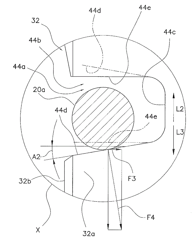
[0086] (a) In the above embodiment, the pinion gear 32 is rotatably and axially movable supported by the reel main body 1 via two bearings, but the present invention is not limited thereto. The present invention can also be applied to a structure in which the pinion is rotatably and axially movable by only one bearing.

[0087] (b) In the above embodiment, the outer diameter of the constricted portion 46 is larger than the outer diameter of the second support portion 50 , but the outer diameter of the constricted portion 46 may be smaller than the outer diameter of the second support portion 50 instead.

...


PUM


Abstract

The invention provides a dual-bearing reel and a clutch mechanism thereof, and clutch disengagement operation can be performed quickly even when a stronger load is applied to the clutch mechanism. The clutch mechanism (13) includes a clutch portion (20) and a pinion gear (32). The pinion gear has an engaging part (44a) and a gear part (48). The engaging part is located on a first end (32b) as a spool-side end of the pinion gear and is capable of being engaged with the clutch portion. The gear part is meshed with the drive gear. The gear part has helical teeth enabling the pinion gear to be urged toward the spool (12) by the drive gear. The engaging part has a bottom (44c) and a first wall (44d). The first wall extends from the bottom toward the first end and tilts in the same direction as the helical teeth with respect to the spool shaft (16) such that the pinion gear is urged oppositely to the spool by the clutch portion when the engaging part is engaged with the clutch portion and receives transmission of rotation in a fishing-line releasing direction from the spool.

Description

technical field [0001] The present invention relates to a dual bearing reel and a clutch mechanism for a dual bearing reel that transmits and cuts off rotation from a handle via a drive gear relative to a spool that is relatively The main body of the reel is free to rotate around the reel shaft in the dual-bearing reel. Background technique [0002] The dual-bearing reel is provided with a rotation transmission mechanism capable of transmitting the rotation of the handle to the spool, and a clutch mechanism arranged in a transmission path of the rotation transmission mechanism. The rotation transmission mechanism has a drive gear provided on a drive shaft that rotates integrally with the handle, and a pinion that meshes with the drive gear. The pinion gear is provided to be able to rotate freely around the spool shaft and freely move in the axial direction. The clutch mechanism has a clutch pin provided on the spool shaft and an engagement groove formed on the pinion. The...

Claims


Application Information

Patent Timeline
Patent Type & Authority Applications(China)
IPC IPC(8): A01K89/015
CPCA01K89/015A01K89/01902A01K89/0188A01K89/01931A01K89/0186A01K89/006
Inventor 生田刚新妻翔渡会悦义吉田贤二
Owner SHIMANO INC
Why Eureka
Try Eureka