A special mounting rod for a U-shaped seat

A kind of installation rod, U-shaped technology, applied in the direction of overhead line/cable equipment, etc., can solve the problems of high work intensity and hidden dangers for the safety of operators, and achieve continuous stability, service level improvement, good economic benefits and social benefits. benefit effect

Active Publication Date: 2017-06-16
国网山东济南市历城区供电公司 +1
View PDF5 Cites 0 Cited by
  • Summary
  • Abstract
  • Description
  • Claims
  • Application Information

AI Technical Summary

Problems solved by technology

Because the power distribution line is long, if the bird repellent is installed according to the current installation method of the bird repellent, and at the same time limited by the small number of personnel, multiple power outages are required. On the one hand, it will bring a lot of inconvenience to electricity customers, on the other hand , During the installation process, it is necessary to climb to the top of the tower to operate. The whole process is not only intensive but also poses a major hidden danger to the safety of operators.

Method used


Image

  • A special mounting rod for a U-shaped seat
  • A special mounting rod for a U-shaped seat

Examples


Embodiment approach 1

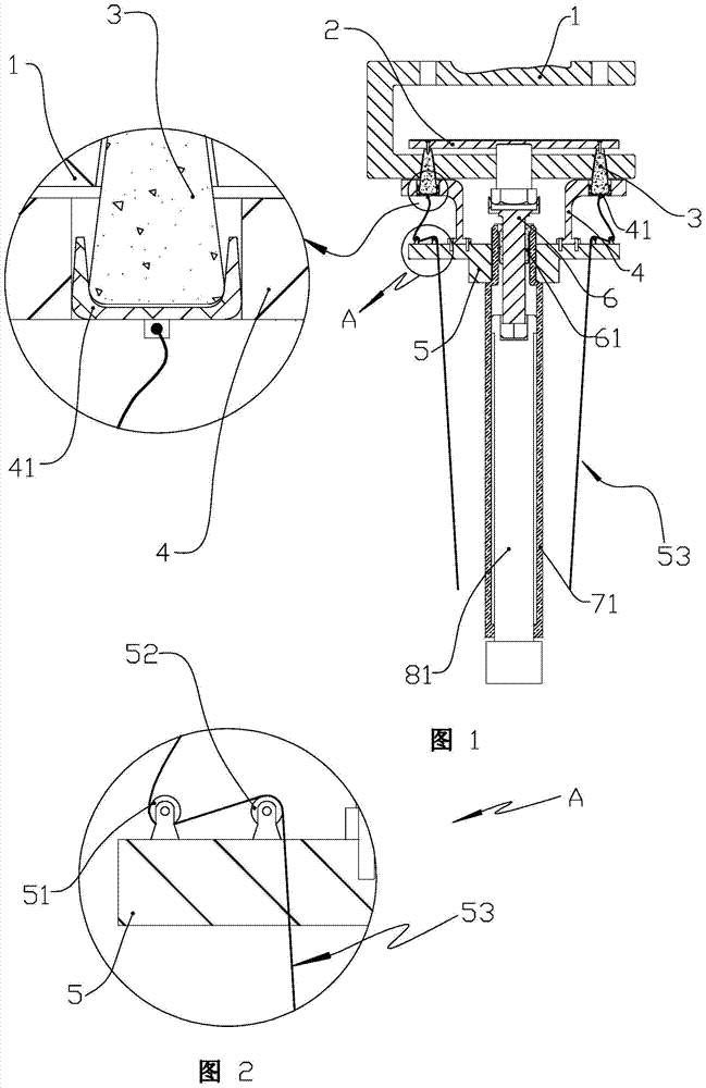
[0027] A special mounting rod for a U-shaped seat as shown in FIGS. 1 and 2 includes two L-shaped bracket arms 4, a support platform 5, a fastening rod 6, an outer rod-71 and an inner rod-81. The U-shaped seat 1 of the bird repellent it is aimed at includes a pressing plate 2 and a tapered column 3 connected on the pressing plate. Make the tapered column 3 pass through from bottom to top in the tapered hole on the lower arm of the U-shaped seat. Obviously, the axial length of the tapered column will be greater than the axial length of the tapered hole, and the taper of the two is consistent. Furthermore, it needs to be emphasized that the working principle of the tapered column is |: the hardness value of the metal material made of the tapered column is smaller than the hardness value of the material made of the U-shaped seat, so that when the tapered column is subjected to upward push and pull, the cone The column will be squeezed by the tapered hole to produce shrinkage defo...

Embodiment approach 2

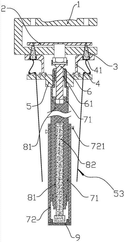
[0040] Such as image 3As shown, the difference from the above-mentioned embodiments is that in this embodiment, the axial length of the special installation rod can be adjusted. For this reason, it is also provided with two outer rods 72 and two inner rods 82, and the structures of the outer rod one 71 and the inner rod one 81 have been adapted and improved.

[0041] The second inner rod 82 is a hexagonal prism rod, and the second outer rod 72 is a tubular rod with an axially extending cylindrical cavity. The cylindrical cavity diameter of the second outer rod 72 is consistent with that of the first outer rod 71 .

[0042] An axial hexagonal prism hole is set from the lower end surface of the inner rod one 81, so that the inner rod two 82 can move axially in a straight line in the hexagonal prism hole of the inner rod one 81, and rotate the inner rod 82 can drive the inner rod 1 81 to rotate around the axis, so that the outer rod 2 72 can move axially and linearly relative t...


PUM


Abstract

A special mounting rod for a U-shaped seat. The L-shaped support arm and the fixed pulley block are installed on the left and right sides of the support platform. The horizontal arm of the L-shaped support arm is provided with a through hole for a rubber cup. The outer wall of the rubber cup is Conical with the big end facing down, the inner cavity is a conical cavity and the cavity is gradually closed from top to bottom. One end of the drawstring is fixed to the rubber cup, and the other end is looped around the first pulley and the second pulley in turn, and hangs down freely to support The table is sleeved on the upper end of the outer rod one. The inner rod one can move axially and rotate in a straight line relative to the outer rod one. One is for axial linear movement and axial rotation, and an axial hexagonal blind hole is arranged on the upper end surface. The special mounting rod and the U-shaped seat with a special structure on the bird repellent are fixed together through the connection between the tapered column on the U-shaped seat and the L-shaped support arm, which can realize the installation of the live work of the bird repellent, and solve the current problem The problem of long power outages for bird repellent installation.

Description

technical field [0001] The invention relates to the field of power transformation application equipment, in particular to a special mounting rod for a U-shaped seat used for installing the U-shaped seat at the lower end of a bird repellent. Background technique [0002] Since the power supply lines are mostly located in the suburbs and are elevated, the duration of the power supply lines will be "harassed" by birds' nesting. According to statistics, the faults of power distribution lines caused by bird nesting have been on the rise in a straight line in recent years. The reason is related to the current indiscriminate logging and the continuous expansion of human activities. Birds nesting on power supply towers will seriously threaten the safe power supply of power distribution lines, so effective measures must be taken to stop them. At present, it is mainly to clean up the bird's nest after finding the bird's nest during line inspection, which is far from enough to realize...

Claims


Application Information

Patent Timeline
Patent Type & Authority Patents(China)
IPC IPC(8): H02G1/02
Inventor 徐大伟张洪峰赵建伟刘双喜刘伟洲李希玉庄力行
Owner 国网山东济南市历城区供电公司
Why Eureka
Try Eureka